bookmark_borderHow to Clone Your Windows 10 Installation USB Drive to Another USB Drive

I recently purchased and installed the retail version of Windows Pro on my primary desktop machine. The installation media came on a USB flash drive. I like to keep backup copies of the Windows installation media, preferable at on offsite location in case I need to reinstall the operating system and the original media is unavailable for some reason. This post described how to clone this USB flash drive. Software versions used in this post were as follows:

  • Windows 10 Pro (x64)
  • ImageUSB, version 1.3.1004

So let’s get started…

To clone the Windows 10 installation media we’re going to use ImageUSB. ImageUSB is a free utility from PassMark software which lets you create on image file from a USB flash drive and then write that image to one or more USB flash drives.

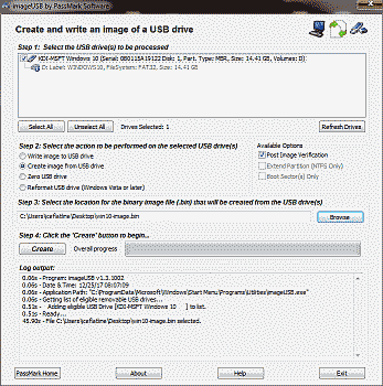
Begin by downloading ImageUSB, then unzip and copy the files to a location of your choice. Insert the Windows 10 USB flash drive into an available USB port then double-click on the file imageUSB.exe. Select the Windows 10 USB flash drive that appears under “step 1”, then select the option to “Create the image from USB drive” under “step 2”. Under the “Available Options” section ensure that the “Post Image Verification” option is selected so that ImageUSB can verify the integrity of the image after it writes it. ImageUSB needs a location and file name to write to; select both under “step 3”. In this example, we’ll write the image to C:/Users/iceflatline/Desktop/win10-image.bin. Now select “Write” under “step 4” and ImageUSB will write the image file (See Figure 1).

Screenshot showing how to create an image of a USB drive in ImageUSB

Figure 1

Once ImageUSB completes writing your image remove the Windows 10 USB flash drive and insert the USB flash drive you want to write win10-image.bin to into an available USB port. Note that this drive must be formatted with suitable file system (e.g., exFAT or NTFS) and have sufficient space available to contain the Windows 10 image (~16 GB). This space will be inaccessible on the USB flash drive after the writing process; however, any remaining space will be accessible.

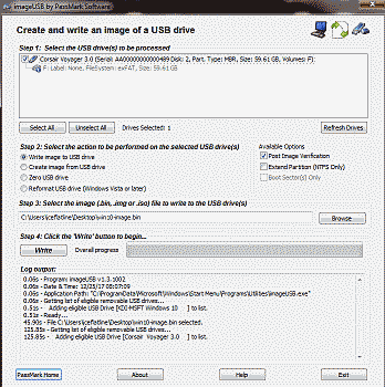
Select “Refresh Drives” in ImageUSB, and select the USB flash drive under “step 1”, then select the option to “Write the image to USB drive” under “step 2”. Again, ensure that “Post Image Verification” is enabled. Select “Browse” in “step 3” and navigate to C:/Users/iceflatline/Desktop/win10-image.bin. Now select “Write” under “step 4” and ImageUSB will write the win10-image.bin to the USB flash drive (See Figure 2).

Screenshot showing how to write an image to a USB drive in ImageUSB

Figure2

Verify that your computer can boot to the backup copy of the Windows 10 installation media and then store the USB flash drive in safe location. Note that ImageUSB can only write *.bin files created with ImageUSB.

Conclusion
ImageUSB is great tool for creating exact bit-level copies of USB flash drives, including those containing Windows 10 installation media.

bookmark_borderHow to Transfer Your Steam Games From One PC to Another

iceflatline decided to build a new gaming PC. iceflatline was also in the middle of several Steam-based games on his current gaming PC. iceflatline really wanted play those games on his new PC, not his old PC. This post describes how iceflatline transferred those Steam games from his old PC to his new PC without losing any game play progress.

Software versions used in this post were as follows:

  • Windows 10 Pro, version 1709
  • Steam client application, build 20171215

So let’s get started…

  • On your old PC navigate to your Steam directory and copy the steamapps subdirectory and all of its contents somewhere you can access from the new PC. The Steam directory is typically located in C:\Program files (x86)\Steam.
  • On your old PC copy your games’ saved game directories (e.g., C:\Users\your-user-name\Documents\My Games\some-game\) and all of their contents to somewhere you can access them from the new PC.
  • On your new PC, install Steam and launch it once, then exit.
  • On your new PC, navigate to the Steam directory and delete everything in it except the file Steam.exe.
  • Copy and paste the steamapps directory you backed up from the old PC to the Steam directory in the new PC and launch Steam. After a brief self update Steam should show your games as installed in the Steam library.
  • Launch one of the games and verify it works. You likely won’t see your characters, saved games, etc – that’s okay. Quit the game.
  • Copy and paste the saved game directories and files you backed up from the old PC to the same locations on the new PC (e.g., C:\Users\your-user-name\Documents\My Games\some-game\).
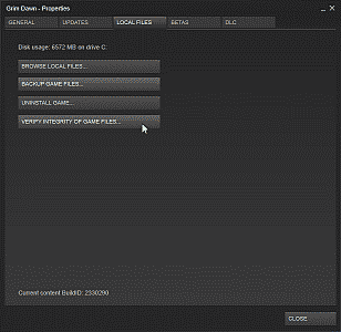
  • Right-click on one of the games in the Steam library, select properties, then select the Local Files tab. Now select Verify Integrity of Game Files (See Figure 1). Let that process run to completion. Now start the game again and your characters, saved games, etc should be there. Rinse and repeat for each game you’ve installed.

Screenshot showing the Local Files options under a game's properties settings in Steam

Figure 1

Game on!

bookmark_borderRun a Windows Application as a Service with srvany

Occasionally the need arises for running an application in Windows as a service. This allows the application to run at boot time without the need for a user to be logged into the system in order for the application to start and operate. While built-in mechanisms such as Task Scheduler exist to help facilitate this, the ability to run an application as a service has certain advantages, notably the ability to prescribe certain actions be taken should the service fail. Take for example the the case where an application is listening for incoming IP connections. Being able to automatically restart the service without user intervention is desirable in order to avoid loss of service.

This post will describe how to use the Microsoft utilities instrsrv.exe and srvany.exe to install a Windows application as a service. instrsrv.exe is used to install the service while srvany.exe acts as a wrapper around the application and handles the service events. Both utilities are available as part of Microsoft’s Windows Server 2003 Resource Kit Tools. I have successful tested instrsrv.exe and srvany.exe on Windows 7/8.1; I have not tested them on Windows 10.

Let’s get started…

For purposes of example, we’ll assume we have a Windows application called “foobar” that is normally started by using the binary c:\foo\foobar.exe.

Start by downloading Microsoft’s Windows Server 2003 Resource Kit Tools and install it to a folder of your choice. Create a folder to contain the files instrsrv.exe and srvany.exe. We’ll use c:\srvany for our example. Now copy both files from the where you installed the Resource Kit tools to c:\srvany. After the files have been copied the Windows Server 2003 Resource Kit Tools may be uninstalled.

Now open a command prompt and install foobar as a system service using the following command. You may use any name you’d like for the service:

You should receive a response indicating that the service was successfully added.

Next, open the Windows registry editor and navigate to HKEY_LOCAL_MACHINE\SYSTEM\CurrentControlSet\services\foobar. Use the mouse or keyboard to highlight foobar and select Edit->New->Key to create a new key named Parameters. Highlight Paramters and select Edit->New->String Value to create a new string value named Application. Double-click on Application and enter the full path to foobar.exe (e.g., c:\foo\foobar.exe). That’s it. You can now close the registry editor.

By default, the newly created service foobar is configured to run automatically when the system is restarted. To change this setting to Manual, run the Services applet by entering services.msc from a command prompt or by using WIN+R. Locate foobar from among the list of services, right-click on it and select Properties and change its Startup type to Manual. A service set to Manual can be started from within the Services applet, or by entering the following from a command prompt:

Selecting the Recovery tab from within properties will allow you to chose what the system should do in the event if the service fails.

You can delete the service by entering the following from a command prompt:

There you have it. A nice simple way to register and run a non-service application as a windows service.

bookmark_borderHow To Access Your VirtualBox Guest VM From The Host Using SSH

(20180430 — The steps in this post were amended to address changes in recent versions of software — iceflatline)

Recently I had the occasion to spin up a Ubuntu server Virtual Machine (“VM”) in VirtualBox on a Windows-based host machine. Those of you who have performed a similar excercise know that the default window size that VirtualBox provides to command-line-based VMs, like *BSD and Ubuntu server, etc., is rather small, somewhere in neighborhood of the standard VGA resolution of 640 x 480 pixels. Normally the fix for this, of course, would be to install what VirtualBox calls “Guest Additions,” which consists of device drivers and other applications that optimize the guest operating system for, among other things, the ability to enlarge the window size. However, getting Guest Additions to install and run properly on command-line-based guest VMs is a monumental pain in the ass. One work-around that seems to work fairly well is to switch the VM window to “scale mode” (View->Switch to Scale Mode or Host+C), resulting in what is essentially a magnified version of the window and its contents. An even better solution, in my opinion, is to configure the VM so that you can connect to it directly from the host machine using Secure Shell (“SSH”), giving you full control over the window and text size of the guest VM.

This post explains how to access a VirtualBox Ubuntu server guest VM from the VirtualBox host machine using SSH. It then goes on to explain how to accomplish the same task when using a FreeBSD guest VM. The software versions used in this post were as follows:

  • FreeBSD 11.0-RELEASE
  • Ubuntu Server 18.04 LTS
  • VirtualBox 5.2.6

Let’s get started…

First, let’s add a new “VirtualBox Host-Only Ethernet Adapter” in VirtualBox. This new adaptor will allow us to enable a private network consisting of our host machine and our guest VM. The host can connect to any guest VMs configured to use this adaptor, and they can connect to each other, but nothing outside of this virtual network will be permitted access.

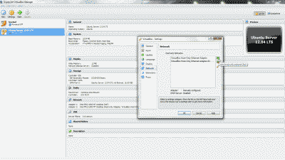
Navigate to Files->Preferences->Network and click on the “+” icon to add new adaptor. You’ll see that VirtualBox creates a new adaptor called “VirtualBox Host-Only Ethernet Adapter #2” (See Figure 1).

Screenshot showing the creation of a VirtualBox Host-Only Ethernet Adapter in VirtualBox

Figure 1

Right now you might be thinking “but couldn’t I just use the existing default VirtualBox Host-Only Ethernet Adaptor?” You absolutely could; however, setting up a second one allows you to customize it to your liking, leaving the default adaptor in its default configuration as a fallback.

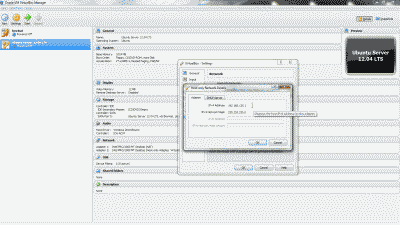
Now, double-click the new adaptor (or highlight it and select the edit icon) and note the IP address and subnet mask (e.g., 192.168.135.1 and 255.255.255.0) that VirtualBox has arbitrarily assigned under the “Adapter” tab. You may change these network parameters if desired, however, it is preferable to retain “1” as the value of the last octet in the IP address (See Figure 2).

Screenshot showing the IP address and subnet mask assignment in the VirtualBox Host-Only Ethernet Adapter #2

Figure 2

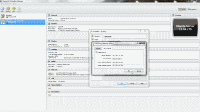
Optionally, you may configure a DHCP server on the VirtualBox Host-Only Ethernet Adapter #2 so that the guest VM obtains an IP address automatically at boot time. This can be accomplished by navigating to Files->Preferences->Network, double-clicking the new adaptor (or highlighting it and selecting the edit icon), selecting the “DHCP Server” tab and the selecting “Enable Server”. You’ll then need to modify the various DHCP server parameters (e.g., Server Address, Server Mask, etc.), keeping in mind that they should encompass the IP address configured for the adaptor, else the IP address should be modified so that it lies within the DHCP server parameters you’ve configured. When finished, select “OK” (See Figure 3). Note: I typically forgo using the DHCP server, electing instead to use a static IP address. That way, I can consistently use the same address each time I want use SSH to connect to the guest VM.

Screenshot showing the DHCP server configuration tab in the VirtualBox Host-Only Ethernet Adapter #2

Figure 3

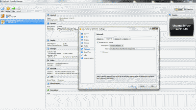
Let’s configure our Ubuntu server VM so that it will use the new VirtualBox Host-Only Ethernet Adapter #2. Shutdown the Ubuntu server VM if it’s running. Right-click on the VM and select Settings->Network. Select the “Adapter 2” tab, then select “Enable Network Adapter”. From among the options under “Attach to:”, select “Host-Only Adapter”, then select “VirtualBox Host-Only Ethernet Adapter #2” from among the options under “name:”. Now select “OK” (See Figure 4).

Screenshot showing the selection of VirtualBox Host-Only Ethernet Adapter #2 for use by the Ubuntu server virtual machine

Figure 4

Now start the Ubuntu server VM. After the system has fully booted, login to the VM at the VirtualBox console window and execute the command ifconfig -a to list all network devices. In addition to your primary network device, enp0s3 (in this example), you should now see a second network device listed, enp0s8 (in this example). If you chose to setup a DHCP server when creating VirtualBox Host-Only Ethernet Adapter #2, then enp0s8 should already have an IP address assigned to it from among the pool of addresses you chose to use with setting up the DHCP server, in which case you should make a note of this address and use it to connect to the Ubuntu server VM using SSH.

If you elected not to setup a DHCP server when creating VirtualBox Host-Only Ethernet Adapter #2, then you’ll need to assign a static IP address to network device enp0s8. First, install the package ifupdown:

Then open /etc/network/interfaces as the root user and add the following lines, making sure to change the values shown in this example so that they fall within the IP subnet parameters chosen when creating the new VirtualBox Host-Only Ethernet Adapter #2:

Now start the interface so that it obtains the new network parameters:

At this point you should be able to connect to the Ubuntu server VM via SSH using this static IP address.

FreeBSD Guest VM

A similar approach can be taken for a FreeBSD guest VM. The setup and configuration of the VirtualBox Host-Only Ethernet Adapter in VirtualBox is identical to what has been described thus far for the Ubuntu server VM. However, in order to assign a static IP address to the new network interface, em1 in the case of FreeBSD, you’ll need to open /etc/rc.conf as the root user and add the following line, making sure to change the values shown in this example so that they fall within the IP subnet parameters chosen when creating the new VirtualBox Host-Only Ethernet Adapter #2:

Then restart the interface so that it obtains the new network parameters:

Conclusion

The default window size that VirtualBox provides to command-line-based guest VMs like BSD and Ubuntu servers is typically very small, resulting in a poor user experience for those administrators trying to perform work beyond just a few quick simple commands. Fortunately, VirtualBox can be configured so that the user can connect directly to a guest VM from the host machine using SSH, giving the user full control over window and text sizing.

bookmark_borderPC Build: Intel Core i7 Ivy Bridge

Time once again to upgrade my desktop computer. My current system, an ASUS P67 Sabertooth motherboard (P67 Chipset/Socket 1155), Intel Core i7-2600K (Sandy Bridge) processor, AMD Radeon HD 6950 GPU, and 8 GB of DDR3-1600 G.Skill RAM, served me well, but I wanted to move on to Intel’s “Ivy Bridge” architecture. This post will document my upgrade, starting with the parts I selected and why; the assembly of the system and the challenges I encountered; and finally, a few thoughts on overclocking the upgraded system.

The Parts

In keeping with previous builds, my goal was to use the best quality components I could find for a reasonable price, and build a good, fast, and reliable machine for PC gaming. In other words, build a machine that’s represents a good value.

The Case – I looked for a mid-tower case that featured good air flow and plenty of room for wiring. The NZXT Tempest case I used for my Sandy Bridge build had served me well, but turned out to be a a bit constraining when it came to routing wiring and keeping the inside of the case looking neat. This time I settled on the Corsair Graphite Series 600T. The 600T is a mid-tower in height, but nearly 11 inches wide. Pre-cut holes with rubber grommets in the motherboard tray combined with plenty of room behind it allowed for clean, uncluttered cable routing; and the dual 200mm fans located at the top of the case assisted in providing very good cooling.

The Power Supply – I decided to go with the Corsair TX750 V2. Corsair’s power supplies are quality products, featuring a single dedicated, single +12V rail for maximum and efficient power distribution and they’re sensibly priced. The unit is 80 PLUS Bronze certified (> 80% efficient) and quiet.

The Processor – After doing a little research and giving it much consideration, I chose the Intel Core i7-3770k processor with a 3.5 GHz base clock frequency, 3.9 GHz maximum default “turbo” frequency, and 8 MB of L3 cache and hyper-threading. Besides the featuring the highest clock frequency among the mid-range Ivy Bridge socket 1155 desktop processors, the “K” suffix means the “turbo mode” multipliers are fully unlocked, giving this processor a lot of overclocking potential.

The Motherboard – The ASUS Sabertooth P67 board meet my needs so well for my Sandy Bridge build that I decided to turn to them once again, selecting the Sabertooth Z77 board for this build.

The Heatsink – After doing a bit a research to make sure it would clear the surrounding components on the motherboard, including the RAM, I chose the Cooler Master Hyper 212 Plus. To improve its already very good cooling capabilities, I purchased an additional Cooler Master 120 mm fan to match the fan the product shipped with and then set it up in a push/pull configuration. This configuration combined with the Corsair case provides very good overall processor cooling. Finally, to ensure that both fans would rotate at reasonably the same speed, I used a PWM splitter from Rosewill to power and control both fans from the processor fan header.

The RAM – I was looking to upgrade to 16 GB of RAM this time around, with timings as low as possible. A factor that I was again glad I considered ahead of time was whether the RAM would fit under the processor’s fan/heatsink due to the close proximity of the RAM slots to processor. I ended up eliminated a couple of products (Corsair’s “Dominator” as an example) because they were simply too tall to fit. Finally I ended up selecting G.Skill’s RipjawsX DDR3-1866 16 GB kit (4 * 4GB), which runs at 1.5v with timings specified at 9-10-9-28.

The Graphics – I with AMD again. After doing looking at some online comparisons, choosing Gigabyte’s version of AMD’s Radeon HD 7870, the GV-R787OC-2GD. At ~$360, it provided the best performance for the money. Indeed, given my 24-inch Dell monitor’s 1920 * 1200 resolution, this GPU should easily handle nearly any game I throw at it.

The Hard Drives – With this build I decided to step up the size and performance of the SSD drive and selected a 2.5-inch OCZ Vertex 4 120 GB SATA 6 Gb/s drive. This will serve as my system drive, containing the operating system and a few of my most used applications and games, while a Western Digital Caviar Black 1TB 7200 RPM 64MB cache SATA 3.0 drive will hold the bulk of my non-OS data.

The Optical Drive – Yup, still use one of these :). In this case, the venerable ASUS DRW-24B1ST.

The Operating System – Not much of a surprise here, I went with Windows 7 Pro 64-bit. The Home Premium version doesn’t support Remote Desktop connections from another computer, a feature I use daily, and this of course is my gaming rig, leaving a Linux out of the hunt (for now). Besides, I get my *nix on using my laptop, which is setup to dual boot windows and several Linux distros, as well as various other machines I administer.

The Build

Time to put those parts to some use. I typically build my systems outside of the case first, then when I’m sure everything is running well, I’ll place the components in the case and dress up the wiring (See Figure 1).
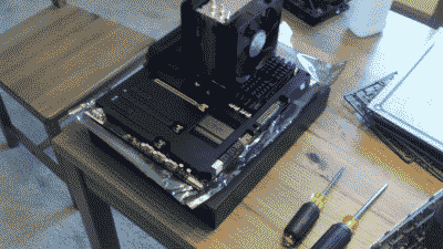
Screenshot of my Intel Core i7 Ivy Bridge build outside of the computer case

Figure 1

The SATA 3.0 and SATA 6.0 ports on the ASUS Z77 are mounted horizontally on the board, making it easier to connect/disconnect disk drives with graphics cards in place. I connected the 120 GB OCZ Vertex 4 drive to the SATA 6.0 GB port 1, and the 1TB WD Caviar Black drive on the SATA 6.0 port 2. These are the Brown SATA ports on the ASUS Sabertooth Z77 motherboard.

When mounting the Cooler Master Hyper 212 Plus, I was able to achieve the lowest processor temperatures by applying two thin lines of thermal compound, in this case, Artic’s Silver 5, to the two center mounting base partitions heat sync (See Figure 2). My idle temperatures are hovering around ~28C when measured in UEFI and approximately the same when measured from within Windows using Real Temp.
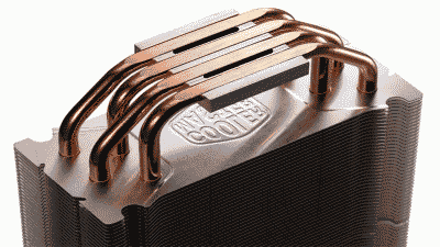
Screenshot showing where to apply thermal compound on the Cooler Master Hyper 212 plus heatsink

Figure 2

The Sabertooth motherboards are equipped with what ASUS calls “TUF Thermal Armor,” a marketing term that ASUS uses to denote what is essentially a large heatsink that encompasses nearly the entire motherboard. The idea behind this unorthodox design is to conduct the hot air generated by cards and components out of the case through special air flow channels, thus reducing the overall temperature of the motherboard, and by extension the inside the the PC case. To do this effectively, however, ASUS recommends that system builders use a processor fan that directs air downward into the motherboard. Unfortunately, like most processor fan/heatsink products made for the PC enthusiasts market, the Cooler Master Hyper 212 Plus is mounted vertically, directing air out the back of the case, not downward towards the motherboard’s components. In anticipation of the situation, ASUS provides a small 50mm fan and a spot on the motherboard to mount it in order to improve the air flow through the TUF Thermal Armor.

After successfully assembling the components, and firing up the system without issue, I proceeded to update the Z77’s UEFI firmware to the latest version. Fortunately ASUS makes this task incredibly easy, offering a number of ways to perform the update, including directly from Windows. I chose to perform the update directly from within the UEFI. First, I downloaded the latest firmware code to a USB flash drive, then inserted the drive into a USB 2.0 port. I entered the “Advanced Mode” of UEFI, navigated to the “Tool” menu, and selected “ASUS EZ Flash Utility.” I highlighted the USB drive containing the ROM file and selected “Enter” to proceed with the UEFI firmware update.

Before installing the operating system on the OCZ Vertex 4 drive, I decided to do a little research on what it would take to update its firmware from version 1.3 to 1.4, which I understood from the OCZ forums would yield better performance from the drive. I’m glad I did, for as it turned out, the version 1.4 firmware update is destructive; meaning if I had gone through process of installing the OS, the update would have simply deleted it. Therefore, performing an update required attaching the drive to another Windows-based machine.

Then I encountered another challenge. The OCZ firmware update tool would indicate that the firmware had updated successfully to version 1.4 and to reboot; however, the tool would then continue to indicate the firmware was version 1.3. The work-around for this problem was odd but it worked. First, I booted the machine. Then I unplugged the power cable from the back of the drive, waited a couple of minutes, and plugged the power back in. Then I proceeded with the update. Once updated, I rebooted and the update tool reported the firmware had indeed successfully updated to version 1.4. It appears the effort was worth it however. A quick look at the performance of the drive using the ATTO Disk Benchmark indicated sequential reads/writes of 476 MB/384MB respectively using 128 KB transfer size.

After successfully installing Windows 7 and all of the device drivers installed, Window’s Device Manager still indicated that a driver for the “PCI Simple Communications Controller” was still missing (The dreaded yellow exclamation mark). It turned out to be a simple fix, but one I always seem to forget to do – download and install Intel’s Management Engine Interface utility from ASUS.

Finally, to improve the reliability of the Z77 Sabertooth’s Ethernet interface I downloaded and installed Intel’s driver for the 82579 Ethernet network interface controller on the Z77. Then, I entered the UEFI’s Advanced mode, navigated to Advanced -> APM and enabled “Power On By PCI” to activate the board’s Wake-on-LAN feature.

With these issues out of way I continued on, updating Windows, adding applications, tweaking options and generally letting the system burn-in for a bit. Then it was time to move on to overclocking the system.

The Overclock

By default the Core i7-3770K runs at 3.5GHz but can turbo boost itself to 3.9GHz if all four cores are not being utilized, and assuming it is operating within what Intel feels are acceptable power and temperature limits. However, Like all of Intel’s “K”suffix processors, the i7-3770K is multiplier-unlocked – this time up to 63x compared to 57x on the Sandy Bridge Core i7-2770K. Therefore, assuming the BCLK bus is running at its default of 100MHz, you could theoretical achieve a maximum CPU speed of the 6.3GHz simply by adjusting the multiplier, assuming of course that you had the necessary cooling solution.

For this build I took a much more conservative route. Not unlike most of the “enthusiasts” motherboards on the market today, the Sabertooth Z77 offers a method to automatically overclock your system, dispensing with the need in most cases to independently adjust BCLK, multiplier, memory, and voltage settings. In fact, the Z67 offers two methods: one is available by navigating to the in the UEFI’s “EZ Mode” settings and selecting the “Performance” option. The other is available by navigating to Advanced Mode -> Ai Tweaker and selecting “OC Tuner.” I decided to give the EZ Mode Performance option a go and was quite happy with the results (See Figure 3).
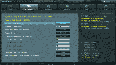
Screenshot of the ASUS Sabertooth Z77 Ai Tweaker settings after invoking the "Performance" option in EZ Mode

Figure 3

The BCLK was increased to 103 MHz and the Turbo Mode multiplier for all four cores to 41. This resulted in an overall processor speed of ~4.2 GHz when running in Turbo Mode. My DDR3-1866 memory essentially remained unchanged. Like I said, conservative. But fast enough for the time being, with plenty of headroom to make further increases in the future if desired.

Next, I adjusted my memory timings to the 9-10-9-28 and ran Memtest86+ for a couple of passes to ensure those timings and the memory in general was sound. Then I ran the 64-bit version of Prime 95 using the “Large in-place FFT” setting for ~24 hours to ensure that the system stability and maximum processor core temperatures were kept in check. I should note that ambient room temperature during the Prime 95 testing was ~21 C. The tests resulted in no errors and the maximum processor core temperatures peaked at ~86 C but on average were ~80C. (See Figure 4).
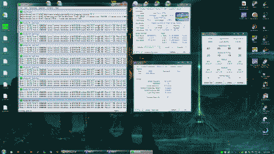
Screenshot of my desktop showing Prime 95, CPU-Z and Real Temp running simultaneously

Figure 4

Conclusion

I couldn’t be more pleased with this build. Intel’s Core i7-3770K processor and ASUS’s Sabertooth Z777 motherboard is a solid mid-range combination. Since its completion, the system has been 100% stable.
iceflatline