bookmark_borderHow to Remove Those Old Laptop Stickers

Tired of those old stickers you adorned your laptop with? Me too. No, I don’t mean yours. I’m sure yours are fine; well, except for that Bieber Rocks! one. What were you thinking!? Anyway, here’s couple of tips on how to remove Bieber and his sticky cousins.

Screenshot showing a Lenovo laptop with numerous stickers

First, power down your laptop, unplug it, and close the lid. Try to remove as many of those old stickers by simply peeling them off. Some will come off cleanly, many won’t. Don’t worry if some of the residue is left behind. Now head to your kitchen and grab that good old no-stick cooking spray and apply liberally to a small section of the laptop surface. Don’t be stingy. The idea is to keep the area you’re working on soaked in the stuff for at least 10-15 minutes – the longer, the better though. Make sure to not let it run down the sides and creep into cooling vents, on to your keyboard, etc.

Screenshot showing a can of no-stick cooking spray

Now grab one of those plastic paint scrapers (emphasis on the word plastic here) you’d find at any big-box hardware store and start gently scraping off the remaining sticker residue, reapplying the cooking spray as necessary. Continue working your way across the surface of your laptop by applying the cooking spray, letting it soak in, then gently scraping.

Screenshot showing a plastic paint scraper

Once you’ve exhausted the capabilities of that paint scraper, any remaining residue can usually be removed with a little more cooking spray and a nylon scrubbing pad.

Screenshot showing a nylon scrubbing pad

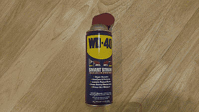
This simple combination of cooking spray, gentle scraping and patience should remove those old stickers and any remaining residue they leave behind. If for some reason the cooking spray isn’t getting the job done for you then WD-40 or a citrus base adhesive remover like goo gone may be a good alternative. Both should be safe to use on your laptop but of course you should test these products first on someplace inconspicuous.

Screenshot showing a can of WD-40

Screenshot showing a bottle of goo gone

As a final step gently clean off the surface of the laptop using a clean wash cloth, warm water and dish washing soap, then dry using a clean cloth or paper towel.

Screenshot showing a Lenovo laptop after stickers have been removed

There you have it. A couple of tips on how to remove those old laptop stickers using materials you can easily find around the house. Do you have more tips or ideas? Leave them in the comment section.

bookmark_borderPC Build: Intel Core i7 Ivy Bridge

Time once again to upgrade my desktop computer. My current system, an ASUS P67 Sabertooth motherboard (P67 Chipset/Socket 1155), Intel Core i7-2600K (Sandy Bridge) processor, AMD Radeon HD 6950 GPU, and 8 GB of DDR3-1600 G.Skill RAM, served me well, but I wanted to move on to Intel’s “Ivy Bridge” architecture. This post will document my upgrade, starting with the parts I selected and why; the assembly of the system and the challenges I encountered; and finally, a few thoughts on overclocking the upgraded system.

The Parts

In keeping with previous builds, my goal was to use the best quality components I could find for a reasonable price, and build a good, fast, and reliable machine for PC gaming. In other words, build a machine that’s represents a good value.

The Case – I looked for a mid-tower case that featured good air flow and plenty of room for wiring. The NZXT Tempest case I used for my Sandy Bridge build had served me well, but turned out to be a a bit constraining when it came to routing wiring and keeping the inside of the case looking neat. This time I settled on the Corsair Graphite Series 600T. The 600T is a mid-tower in height, but nearly 11 inches wide. Pre-cut holes with rubber grommets in the motherboard tray combined with plenty of room behind it allowed for clean, uncluttered cable routing; and the dual 200mm fans located at the top of the case assisted in providing very good cooling.

The Power Supply – I decided to go with the Corsair TX750 V2. Corsair’s power supplies are quality products, featuring a single dedicated, single +12V rail for maximum and efficient power distribution and they’re sensibly priced. The unit is 80 PLUS Bronze certified (> 80% efficient) and quiet.

The Processor – After doing a little research and giving it much consideration, I chose the Intel Core i7-3770k processor with a 3.5 GHz base clock frequency, 3.9 GHz maximum default “turbo” frequency, and 8 MB of L3 cache and hyper-threading. Besides the featuring the highest clock frequency among the mid-range Ivy Bridge socket 1155 desktop processors, the “K” suffix means the “turbo mode” multipliers are fully unlocked, giving this processor a lot of overclocking potential.

The Motherboard – The ASUS Sabertooth P67 board meet my needs so well for my Sandy Bridge build that I decided to turn to them once again, selecting the Sabertooth Z77 board for this build.

The Heatsink – After doing a bit a research to make sure it would clear the surrounding components on the motherboard, including the RAM, I chose the Cooler Master Hyper 212 Plus. To improve its already very good cooling capabilities, I purchased an additional Cooler Master 120 mm fan to match the fan the product shipped with and then set it up in a push/pull configuration. This configuration combined with the Corsair case provides very good overall processor cooling. Finally, to ensure that both fans would rotate at reasonably the same speed, I used a PWM splitter from Rosewill to power and control both fans from the processor fan header.

The RAM – I was looking to upgrade to 16 GB of RAM this time around, with timings as low as possible. A factor that I was again glad I considered ahead of time was whether the RAM would fit under the processor’s fan/heatsink due to the close proximity of the RAM slots to processor. I ended up eliminated a couple of products (Corsair’s “Dominator” as an example) because they were simply too tall to fit. Finally I ended up selecting G.Skill’s RipjawsX DDR3-1866 16 GB kit (4 * 4GB), which runs at 1.5v with timings specified at 9-10-9-28.

The Graphics – I with AMD again. After doing looking at some online comparisons, choosing Gigabyte’s version of AMD’s Radeon HD 7870, the GV-R787OC-2GD. At ~$360, it provided the best performance for the money. Indeed, given my 24-inch Dell monitor’s 1920 * 1200 resolution, this GPU should easily handle nearly any game I throw at it.

The Hard Drives – With this build I decided to step up the size and performance of the SSD drive and selected a 2.5-inch OCZ Vertex 4 120 GB SATA 6 Gb/s drive. This will serve as my system drive, containing the operating system and a few of my most used applications and games, while a Western Digital Caviar Black 1TB 7200 RPM 64MB cache SATA 3.0 drive will hold the bulk of my non-OS data.

The Optical Drive – Yup, still use one of these :). In this case, the venerable ASUS DRW-24B1ST.

The Operating System – Not much of a surprise here, I went with Windows 7 Pro 64-bit. The Home Premium version doesn’t support Remote Desktop connections from another computer, a feature I use daily, and this of course is my gaming rig, leaving a Linux out of the hunt (for now). Besides, I get my *nix on using my laptop, which is setup to dual boot windows and several Linux distros, as well as various other machines I administer.

The Build

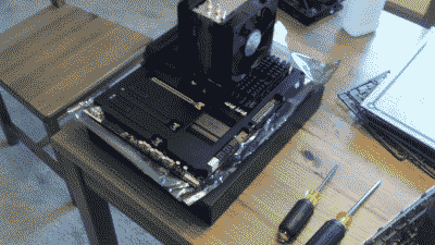
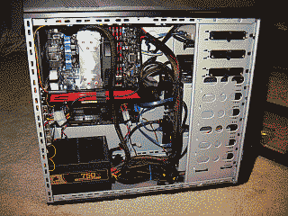
Time to put those parts to some use. I typically build my systems outside of the case first, then when I’m sure everything is running well, I’ll place the components in the case and dress up the wiring (See Figure 1).

Screenshot of my Intel Core i7 Ivy Bridge build outside of the computer case

Figure 1

The SATA 3.0 and SATA 6.0 ports on the ASUS Z77 are mounted horizontally on the board, making it easier to connect/disconnect disk drives with graphics cards in place. I connected the 120 GB OCZ Vertex 4 drive to the SATA 6.0 GB port 1, and the 1TB WD Caviar Black drive on the SATA 6.0 port 2. These are the Brown SATA ports on the ASUS Sabertooth Z77 motherboard.

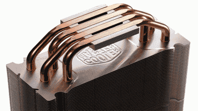
When mounting the Cooler Master Hyper 212 Plus, I was able to achieve the lowest processor temperatures by applying two thin lines of thermal compound, in this case, Artic’s Silver 5, to the two center mounting base partitions heat sync (See Figure 2). My idle temperatures are hovering around ~28C when measured in UEFI and approximately the same when measured from within Windows using Real Temp.

Screenshot showing where to apply thermal compound on the Cooler Master Hyper 212 plus heatsink

Figure 2

The Sabertooth motherboards are equipped with what ASUS calls “TUF Thermal Armor,” a marketing term that ASUS uses to denote what is essentially a large heatsink that encompasses nearly the entire motherboard. The idea behind this unorthodox design is to conduct the hot air generated by cards and components out of the case through special air flow channels, thus reducing the overall temperature of the motherboard, and by extension the inside the the PC case. To do this effectively, however, ASUS recommends that system builders use a processor fan that directs air downward into the motherboard. Unfortunately, like most processor fan/heatsink products made for the PC enthusiasts market, the Cooler Master Hyper 212 Plus is mounted vertically, directing air out the back of the case, not downward towards the motherboard’s components. In anticipation of the situation, ASUS provides a small 50mm fan and a spot on the motherboard to mount it in order to improve the air flow through the TUF Thermal Armor.

After successfully assembling the components, and firing up the system without issue, I proceeded to update the Z77’s UEFI firmware to the latest version. Fortunately ASUS makes this task incredibly easy, offering a number of ways to perform the update, including directly from Windows. I chose to perform the update directly from within the UEFI. First, I downloaded the latest firmware code to a USB flash drive, then inserted the drive into a USB 2.0 port. I entered the “Advanced Mode” of UEFI, navigated to the “Tool” menu, and selected “ASUS EZ Flash Utility.” I highlighted the USB drive containing the ROM file and selected “Enter” to proceed with the UEFI firmware update.

Before installing the operating system on the OCZ Vertex 4 drive, I decided to do a little research on what it would take to update its firmware from version 1.3 to 1.4, which I understood from the OCZ forums would yield better performance from the drive. I’m glad I did, for as it turned out, the version 1.4 firmware update is destructive; meaning if I had gone through process of installing the OS, the update would have simply deleted it. Therefore, performing an update required attaching the drive to another Windows-based machine.

Then I encountered another challenge. The OCZ firmware update tool would indicate that the firmware had updated successfully to version 1.4 and to reboot; however, the tool would then continue to indicate the firmware was version 1.3. The work-around for this problem was odd but it worked. First, I booted the machine. Then I unplugged the power cable from the back of the drive, waited a couple of minutes, and plugged the power back in. Then I proceeded with the update. Once updated, I rebooted and the update tool reported the firmware had indeed successfully updated to version 1.4. It appears the effort was worth it however. A quick look at the performance of the drive using the ATTO Disk Benchmark indicated sequential reads/writes of 476 MB/384MB respectively using 128 KB transfer size.

After successfully installing Windows 7 and all of the device drivers installed, Window’s Device Manager still indicated that a driver for the “PCI Simple Communications Controller” was still missing (The dreaded yellow exclamation mark). It turned out to be a simple fix, but one I always seem to forget to do – download and install Intel’s Management Engine Interface utility from ASUS.

Finally, to improve the reliability of the Z77 Sabertooth’s Ethernet interface I downloaded and installed Intel’s driver for the 82579 Ethernet network interface controller on the Z77. Then, I entered the UEFI’s Advanced mode, navigated to Advanced -> APM and enabled “Power On By PCI” to activate the board’s Wake-on-LAN feature.

With these issues out of way I continued on, updating Windows, adding applications, tweaking options and generally letting the system burn-in for a bit. Then it was time to move on to overclocking the system.

The Overclock

By default the Core i7-3770K runs at 3.5GHz but can turbo boost itself to 3.9GHz if all four cores are not being utilized, and assuming it is operating within what Intel feels are acceptable power and temperature limits. However, Like all of Intel’s “K”suffix processors, the i7-3770K is multiplier-unlocked – this time up to 63x compared to 57x on the Sandy Bridge Core i7-2770K. Therefore, assuming the BCLK bus is running at its default of 100MHz, you could theoretical achieve a maximum CPU speed of the 6.3GHz simply by adjusting the multiplier, assuming of course that you had the necessary cooling solution.

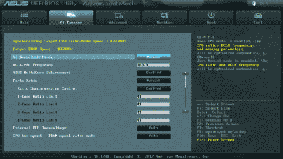
For this build I took a much more conservative route. Not unlike most of the “enthusiasts” motherboards on the market today, the Sabertooth Z77 offers a method to automatically overclock your system, dispensing with the need in most cases to independently adjust BCLK, multiplier, memory, and voltage settings. In fact, the Z67 offers two methods: one is available by navigating to the in the UEFI’s “EZ Mode” settings and selecting the “Performance” option. The other is available by navigating to Advanced Mode -> Ai Tweaker and selecting “OC Tuner.” I decided to give the EZ Mode Performance option a go and was quite happy with the results (See Figure 3).

Screenshot of the ASUS Sabertooth Z77 Ai Tweaker settings after invoking the "Performance" option in EZ Mode

Figure 3

The BCLK was increased to 103 MHz and the Turbo Mode multiplier for all four cores to 41. This resulted in an overall processor speed of ~4.2 GHz when running in Turbo Mode. My DDR3-1866 memory essentially remained unchanged. Like I said, conservative. But fast enough for the time being, with plenty of headroom to make further increases in the future if desired.

Next, I adjusted my memory timings to the 9-10-9-28 and ran Memtest86+ for a couple of passes to ensure those timings and the memory in general was sound. Then I ran the 64-bit version of Prime 95 using the “Large in-place FFT” setting for ~24 hours to ensure that the system stability and maximum processor core temperatures were kept in check. I should note that ambient room temperature during the Prime 95 testing was ~21 C. The tests resulted in no errors and the maximum processor core temperatures peaked at ~86 C but on average were ~80C. (See Figure 4).

Screenshot of my desktop showing Prime 95, CPU-Z and Real Temp running simultaneously

Figure 4

Conclusion

I couldn’t be more pleased with this build. Intel’s Core i7-3770K processor and ASUS’s Sabertooth Z777 motherboard is a solid mid-range combination. Since its completion, the system has been 100% stable.

bookmark_borderPC Build: Intel Core i7 Sandy Bridge

Recently I decided it was time to upgrade my main desktop computer. My current system, featuring an Intel DP55KG motherboard (P55 Chipset/Socket 1156), Intel Core i7-860 (Lynnfield) processor, AMD Radeon HD 5870 GPU, and 8 GB of DDR3-1600 Mushkin RAM, had served me well, but I was anxious to give Intel’s “Sandy Bridge” architecture a try. This post will document my upgrade, starting with the parts I selected and why; the assembly of the system and the challenges I encountered; and finally, a few thoughts on overclocking the upgraded system.

The Parts

As I stated in my previous posts concerning my Lynnfield build, I’ve built a good many PCs over the years. My goal now, as it was then, was to use the best quality components I could find for a low price, and build a good, fast, and reliable machine. In other words, build a machine that’s a good value.

The Case – Thermal management in Intel processors have progressed to the point where unless you’re planning on doing some serious overclocking there’s really no reason to consider using water cooling over a good air cooling solution. Consequently, I was looking for a mid-tower case with good air flow. Since the NZXT Tempest case I used for my Lynnfield build had served me well in this regard, I decided to go with the next generation of this case, the NZXT Tempest Evo. Among other things, this case features dual 120mm intake and 140mm exhaust fans, with an additional side 120mm fan and rear 120mm fan, making it one of the better cases for air cooling. Another nice feature that was added to this case is a slightly wider side panel design, thus increasing the available space behind the motherboard for cable routing, as well as a punchout behind the processor so one doesn’t have to completely remove the motherboard from the case in order to replace the heatsink and fan.

The Power Supply – I’ve almost exclusively used power supplies from two manufacturers: Fortron for lower cost builds and PC Power & Cooling. This time however, I decided to go with the Corsair TX750. This is a slightly less expensive unit than a comparable one from PC Power & Cooling, but Corsair does maintain quality products and this unit still features a dedicated, single +12V rail for maximum and efficient power distribution.

The Processor – With Sandy Bridge Intel launched with no less than 29 different SKUs (15 for mobile and 14 for desktop) once again presenting a very challenging decision for the gamer/enthusiast building a new desktop system. After doing some research and giving it much consideration, I chose the Intel Core i7-2600k processor with a 3.4 GHz core clock, 8 MB of L3 cache and hyper-threading. Besides the featuring the highest core clock among the Sandy Bridge desktop processors, the “K” suffix means the “turbo mode” multipliers, from 16x all the way up to 57x, are fully unlocked, giving this processor a lot of overclocking potential.

The Motherboard – I’ve traditionally used ASUS motherboards but then began to run into reliability problems with them over the years. I also grew tired of the growing list of “features” their boards began to offer that I had no use for on my desktop machines (e.g. WiFi, Bluetooth, etc.), resulting in time spent maintaining drivers for these features or trying to disable them altogether. For my Lynnfield build I used Intel’s DP55KG and really liked it. No it didn’t have all the features and overclocking capabilities of say an ASUS or Gigabyte motherboard at the time, but it turned out to be sufficiently overclockable for my needs and has been 100% reliable. However, The Sandy Bridge processor ushered in yet one more socket change by Intel, Socket 1155, taking the option to use my existing Socket 1156-based Intel DP55KG motherboard off the table. Even so, given my overall good experience with Intel motherboards, I initially decided to go with them again for this build and chose their DP67BG. However, no sooner had this board arrived than Intel announced that they had discovered a design error in the P67 chipset. In some cases, the Serial-ATA (SATA) ports within the chipset may degrade over time, potentially impacting the performance or functionality of SATA-linked devices such as hard disk drives and DVD-drives. Since I had just purchased the product I returned it as defective for a full refund. Then I waited for Intel to roll out the next (so called “B3”) version of this board. Unfortunately that day never came, and Intel showed no sign that they would upate this product, so I once again looked to ASUS to meet my needs and ended up selecting their Sabertooth P67 board, my first I should add that featured a Unified Extensible Firmware Interface (“UEFI”). I also purchased a small 50 mm fan from Evercool to help improve upon the board’s “TUF Thermal Armor” cooling capabilities.

The Heatsink – I chose the Cooler Master Hyper 212 after doing a bit a research to make sure it would clear the surrounding components on the motherboard, including the RAM. To improve its already very good cooling capabilities, I purchased an additional 120 mm fan from Cooler Master that matched the fan the product shipped with and set it up in a push/pull configuration. This fan configuration combined with the NZXT case should provide excellent overall processor cooling. Finally, to ensure that both fans would rotate at reasonably the same speed, I used a PWM splitter from Rosewill to power and control both fans from the processor fan header.

The RAM – I was looking for an 8 GB DDR3-1600 dual kit (2 x 4 GB) with the timings as low as possible. Another factor that I was glad I considered ahead of time was whether the RAM would fit under the processor’s fan/heatsink due to the close proximity of the RAM slots to processor. I ended up eliminated a couple of products (Corsair’s “Dominator” as an example) because they were too tall to fit. I ended up selecting G.Skill’s RipjawsX DDR3-1600 8 GB dual kit, which runs at 1.65v with timings that spec at 7-8-7-24-2N. I had heard and read good things about G.Skill memory and was anxious to finally have the opportunity to give one of their products a try.

The Graphics – I have no particular allegiance to either AMD or Nvidia and was willing to go with a product from either depending on its price versus performance. I ended up going with AMD this time around and chose the MSI R6950 Twin Frozr II OC. For ~$290, I felt it provided the best performance for the money.

The Hard Drives – When I built my Lynnfield-based rig, solid state drive (SSD) prices were still relatively high compared to conventional spindle drives and firmware support for features like “trim” so fluid I decided to stick with with my trusty Western Digital “Raptor” drives. SSD prices have since dropped and trim support is now fully implemented so I decided it was time to upgrade. While I wanted to spring for a new SATA revision 3.0 (SATA 6 Gb/s) drive, I could not justify the cost at this time, so I chose instead the OCZ Vertex 2 80 GB SATA revision 2.0 (SATA 3 Gb/s) SSD. This will serve as my system drive, and a Western Digital Caviar Black 1TB 7200 RPM 64MB cache SATA 3.0 drive will hold my data.

The Optical Drive – Believe it or not I actually still use one of these :). I didn’t spend much time shopping for it though, instead I went to Newegg, navigated to CD/DVD Burners, selected “Best Rating” from among the search options, and dutifully paid for the ASUS DRW-24B1ST.

The Operating System – Not much of a surprise here, I went with Windows 7 Pro 64-bit. Why the Pro version instead of Home Premium? Remote Desktop. Home Premium doesn’t support it and I need this feature so I can access this machine remotely. Why Windows and not Linux? Games. I’m a PC gamer and this is my gaming rig (there are many like it but this one’s mine…). Someday perhaps computer gaming on *nix-based systems will be a viable option. No one hopes that day will will come more than I do, but it’s not today.

The Build

With the component selection and purchase out of the way it was time to put them all together. I like to build systems outside of the the case. Then, when I’m sure everything is running well, I’ll place the components in the case and dress up the wiring (See Figure 1).

Screenshot of my Core i7 Sandy Bridge build outside of the computer case

Figure 1

The SATA 2.0 and SATA 3.0 ports are mounted horizontally, facing the back of the case, instead of vertically, making it much easier to connect/disconnect disk drives with the graphics card in place. I placed the 80 GB OCZ Vertex 2 drive, which will hold the operating system, on the P67 controller’s SATA 3.0 GB port 1, and the 1TB WD Caviar Black drive on the SATA 3.0 port 2. These are the Brown SATA ports on the ASUS Sabertooth P67 motherboard.

The Sabertooth P67 is equipped with what ASUS calls “TUF Thermal Armor,” a rather fancy term for what is essentially a heatsink that encompasses nearly the entire motherboard. The idea behind this somewhat unorthodox design is to conduct the hot air generated by cards and components out of the case through special air flow channels, thus reducing the overall temperature of the motherboard, and by extension the inside the the PC case. To do this effectively, however, ASUS recommends that system builders use a processor fan that directs air downward into the motherboard. Unfortunately, like most processor fan/heatsink products made for the PC enthusiasts market, the Cooler Master Hyper 212 Plus is mounted vertically, directing air out the back of the case, not downward towards the motherboard’s components. In anticipation of the situation, ASUS provides a spot on the motherboard that allows one to mount a small 50mm “assistant” fan, in order to improve the air flow through the TUF Thermal Armor (See Figure 2).
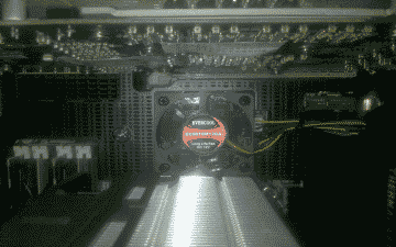
Screenshot of the 50 mm fan from Evercool installed on the ASUS P67 motherboard

Figure 2

After successfully assembling the components, and firing up the system without issue, I proceeded to update the P67 Sabertooth’s UEFI firmware to the latest version. Fortunately ASUS makes updating the firmware incredibly easy, offering a number of ways to perform the task, including directly from Windows. The one that worked best for me was to perform the update directly from within the UEFI. First, I inserted a USB drive contained the latest UEFI ROM file into a USB port. Then I entered the “Advanced Mode” of UEFI, navigated to the “Tool” menu, and selected “ASUS EZ Flash Utility.” I highlighted the USB drive containing the ROM file and selected “Enter” to proceed with the UEFI firmware update.

With updated UEFI firmware now place, it was time to explore the UEFI settings, ensuring that my drives were detected correctly, disabling unwanted features, etc. One issue I noticed fairly quickly was that my processor temperature was idling at ~42C at a room temperature of ~21C, a little hotter than what I would expect when using the Cooler Master Hyper 212 Plus. It should be noted here that on the P67 Sabertooth, the processor temperature reading in the UEFI can be anywhere between ~5C – ~10C higher than in Windows. That’s normal as the UEFI does not send idle commands to the processor, as is the case when the OS is running. Investigating this issue further led me to this Benchmark Reviews article discussing the best thermal paste application methods for heat-pipe direct touch coolers. After a bit of experimentation, I obtained the lowest processor temps using my Cooler Master Hyper 212 Plus by applying two thin lines of Artic Silver 5 thermal compound to the two center mounting base partitions (See Figure 3), lowering my processor temps to ~37C in UEFI and ~31 when measured from within Windows using Real Temp.
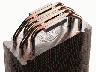
Screenshot showing where to apply thermal compound on the Cooler Master Hyper 212 plus heatsink

Figure 3

Windows Professional (x64) installed without issue on the OCZ Vertex 2 drive, but this is where my progress came to a temporary halt. One of the first applications I typically install shortly after I finish installing the OS is CPU-Z in order to evaluate processor core stepping and core voltage; internal and external processor clocks and clock multipliers; and memory frequency and timings. CPU-Z showed that the processor multiplier was “stuck” at 1.6 GHz (multipler = 16x), never allowing the processor to rise to its specified default operating frequency of 3.4 GHz (multiplier = 34x) or its default Turbo mode frequency of 3.8 GHz (multiplier = 38x). After trying numerous UEFI tweaks, I gave up and concluded that the board was defective. The replacement board was received a week or so later and after reassembling the requisite parts it worked as designed.

Another issue I encountered involved updating the firmware on the OCZ Vertex 80 GB drive to the most recent version – 1.33 at the time of this post. The OCZ Toolbox firmware update tool did not see the SSD drive because the tool is currently incompatible with the Intel Rapid Storage Technology (“RST”) driver software – V10.0.0.1046 at the time of this post. The work around for this problem was to remove the Intel RST driver, update the firmware, then reinstall the Intel RST driver. Incidentally, I took the opportunity to run a few benchmark tests against this drive using ATTO Disk Benchmark and came away with the 272 MB reads and 258 MB writes (128 KB transfer size).

With all of the device drivers installed Window’s Device Manager was still indicating that a driver for the “PCI Simple Communications Controller” was still missing (The dreaded yellow exclamation mark). It turned out that I needed to download and install Intel’s Management Engine Interface utility from ASUS in order to clear that error.

Finally, to improve the reliability of the P67 Sabertooth’s Wake on Lan feature, I decided to download and install the Intel drivers for the Sabertooth P67’s 82579V Ethernet network interface controller. Then, I entered the UEFI’s Advanced mode, navigated to Advanced -> APM and enabled “Power On By PCI.”

With these issues out of way I continued on, updating Windows, adding applications, tweaking options and generally letting the system burn-in for a bit. Then it was time to move on to overclocking the system.

The Overclock

With the advent of Intel’s “Turbo Mode” feature starting in its Nehalem “Bloomfield” processor, the Base Clock (BCLK) multiplier value was able to automatically increase beyond its default value if the processor was operating within what the design considered to be a safe temperature tolerance. For example, in the Bloomfield architecture, processors were allowed to raise the stock multiplier value by 1 or 2 depending on the number of cores being used so long as the processor’s core temperatures did not rise beyond an arbitrary threshold. Intel’s Lynnfield processors generally ran cooler and so were allowed to be considerably more aggressive with Turbo Mode, increasing Turbo Mode multipliers within a range of ~2-5. In practice what this meant was that when fewer processor cores were in demand by a given application or process, larger multiplier values were used, thus allowing the processor to temporarily run at a higher clock rate than the default multiplier would normally allow. In the case of my Core i7 860 for example, with its BCLK of 133 MHz, it was not uncommon to see it use a multiplier value of 26 in single-threaded applications, yielding a processor speed of 3.46 GHz, well above its stock speed of 2.8 GHz when using the default multiplier of 21.

Consequently, when it came to overclocking, the Lynnfield architecture offered the user somewhat of a choice. You could attempt to overclock the system with Turbo Mode enabled, requiring you to be mindful of the headroom necessary when higher turbo multiplier values kicked in, or you could simply disable Turbo Mode and go with the more traditional overclocking approach. Either way, the steps were similar: adjust the BCLK to achieve your desired processor frequency; adjust the memory multiplier to compensate for the change in BCLK; and, if necessary, adjust the processor voltage, memory voltage, and Uncore voltage to stabilize the system; rinse and repeat.

The new Sandy Bridge technology, however, is a bit more challenging when it comes to overclocking. The new 100 MHz BCLK of Sandy Bridge processors doesn’t give users a lot of latitude in terms of increasing its value. If you’re lucky you can get it to run reliably at say 110 MHz. Multiply that value with your maximum Turbo Mode multiplier value, 38 in the case of the Core i7 2600K, and you’ll achieve ~4.2 GHz. Fortunately, with the K series processor, your overclocking options aren’t limited by the BCLK value; you’re also offered an unlocked multiplier ranging from 34 to 57, allowing you to potentially reach much higher processor speeds when operating in Turbo Mode.

Not unlike most of the “enthusiasts” motherboards on the market today, the Sabertooth P67 offers a method to automatically overclock your system, dispensing with the need in most cases to independently adjust BCLK, memory and voltage settings. In fact, the Sabertooth P67 offers two methods: one is available by navigating to the in the UEFI’s “EZ Mode” settings and selecting the “Performance” option. The other is available by navigating to Advanced Mode -> Ai Tweaker and selecting “OC Tuner.” I decided to give the EZ Mode Performance option a go and was quite happy with the results (See Figure 4).
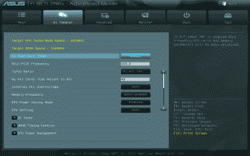
Screenshot of the ASUS Sabertooth P67 Ai Tweaker settings after invoking the "Performance" option in EZ Mode

Figure 4

The BCLK was increased to 103 MHz and the Turbo Mode multiplier for all four cores to 43. This resulted in an overall processor speed of ~4.4 GHz when running in Turbo Mode. My DDR3-1600 memory settled at a speed of 1648 MHz. None of this is going to set any overclocking records, but you know what? It’s plenty fast for me for the time being, with plenty of headroom to make further increases at a later time if desired.

Next, I adjusted my memory timings to the 7-8-7-24 and ran Memtest86+ for a couple of passes to ensure those timings were stable. Then I ran the 64-bit version of Prime 95 using the “Large in-place FFT” setting for ~24 hours to ensure that the system stability and maximum processor core temperatures were kept in check. I should note that ambient room temperature during the Prime 95 testing was ~21 C. The tests resulted in no errors and the maximum processor core temperatures were ~65 C. (See Figure 5).
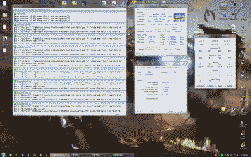
Screenshot of my desktop showing Prime 95, CPU-Z and Real Temp running simultaneously

Figure 5

Conclusion

Intel’s Core i7 2600K processor and ASUS’s Sabertooth P67 motherboard turned out to be a good mid-range combination. Throw in the MSI R6950 Twin Frozr II graphics card and the 8 GB DDR3-1600 dual kit from G.Skill and I couldn’t be more pleased with the results of my first Sandy Bridge build. Since its completion, the system has been 100% stable. Future plans for this system likely include replacing the 80 GB SATA 2.0 drive with a SATA 3.0 drive, and of course do a bit more overclocking.

References
https://www.asus.com/us/Motherboards/SABERTOOTH_P67/

bookmark_borderIntel Core i7 Build: Overclocking the Intel DP55KG and Core i7 860

This is the third post documenting my upgrade to an Intel Core i7 Lynnfield system. In my first post I discussed the components I selected and why. I talked about assembling the system and some of the challenges I encountered in my second post, and in this final post I’ll be discussing my efforts at overclocking the Intel DP55KG motherboard and Core i7 860 processor.

Two Approaches

Intel’s new “Turbo Mode” feature is able to increase the processor multiplier value beyond its default value (21 in the case of the Core i7 860) if the processor is operating within what it considers are safe temperature parameters. For example, in Intel’s Core i7 Bloomfield architecture, processors are allowed to raise the stock multiplier value by 1 or 2 depending on the number of cores being used. Intel’s Lynnfield processors are considerably more aggressive with Turbo Mode, increasing Turbo Mode multipliers within a range of ~2-5. Essentially what this means is that when fewer processor cores are demanded by an application or process, larger multiplier values are used, thus the processor is allowed to run faster than the default multiplier would normally allow. In the case of the Core i7 860, it’s not uncommon, for example, to see it use a multiplier value of 26 in single-threaded applications, yielding a processor speed of 3.46 GHz, well above its stock speed of 2.8 GHz. While this sort of dynamic overclocking is pretty damn impressive, a question arose for me when it came time to overclock my Intel DP55KG and Core i7 860: should I attempt to overclock the system with Turbo Mode enabled, meaning I would have to consider the headroom required when higher multiplier values are used, or should I simply disable it and go with the more traditional overclocking approach? I ended up trying both approaches to see how they compared and to evaluate which would work best for me.

Regardless of which approach you use though, overclocking a Lynnfield system is pretty straight forward. Adjust the host clock frequency until the system achieves a stable CPU speed. From there, the memory multiplier can be adjusted to compensate for the change in host frequency. If desired/needed you can also adjust the CPU voltage, memory voltage, and Uncore voltage to further stabilize the system. That’s pretty much all the adjusting the architecture allows you to do.

    Turbo Mode enabled

My first attempt at overlocking the Intel DP55KG and the Core i7 860 involved raising the host clock frequency but leaving with Turbo Mode enabled. These are the BIOS settings I started with:

Performance

Host Clock Frequency Override: Manual

Performance -> Processor Overrides

CPU Voltage Override Type: Dynamic
CPU Voltage Override: Default (default)
CPU Idle State: High Performance
Intel Turbo Boost Technology: Enabled (default)

Performance -> Memory Configuration

Performance Memory Profiles: Manual – User Defined
Memory Multiplier: 12
Memory Voltage: 1.65
Uncore Voltage Override: 1.10 (default)

Performance -> Bus Overrides

All settings in this section were left at their default values.

Power

Enhanced Intel SpeedStep Tech: Enabled (default)
CPU C State: Enabled (default)

With this approach, my objective was to try to achieve the best stable overclock I could using Turbo Boost and leaving the voltage settings at thier default values. However, I did alter two voltage settings: the CPU Voltage Override Type, which I set to Dynamic, allowing the CPU to still manage its own power usuage but with higher upper limits; and the Memory Voltage, which I set to 1.65 to match the voltage input specified for my Mushkin DDR3-1600 kits. I left the RAM timings at the default SPD values of 9 9 9 24.

And the result? I was able to achieve a host clock frequency of 154 MHz before the system became unstable (stability in this case is defined as the ability for the system to run without failure using Prime95 (v25.9) Large FFT for 2-3 hours). This yielded a CPU speed of 4 GHz, assuming a Turbo Boost multiplier of 26 (154 * 26 = 4.00 GHz). I did notice, however, that the multiplier in my case generally liked to stay at 25 a large percentage of the time during idle. I suspect this was the result of the High Performance setting in BIOS that forces the system to use the higher multiplier when the operating system would otherwise be allowed to lower it.

According to CPU-Z (v1.53) The CPU voltage (VID) fluxuates between .8 and .9 at idle and core temperatures according to Speedfan (v4.40) were ~30c at idle. Given the DRAM multiplier setting of 12, the DRAM frequency weighed in at a nice 1848 MHz. Loading all four cores resulted in VID rising to 1.096 volts and core temperatures to ~63c. Using all four cores of course also resulted in the system using the default CPU multiplier value of 21 (154 * 21 = 3.23 GHz).

So, in summary, I was able to achieve ~15% overclock under load using Turbo Boost and leaving the voltage settings at thier default values.

    Turbo mode disabled

After determining the optimal overlocking settings for my Intel DP55KG and the Core i7 860 using default voltages and Turbo Mode enabled, I attempted to overclock the system with Turbo Burst disabled as well as the freedom to use higher voltage settings, if necessary, to make the system stable. These are the BIOS settings I started with:

Performance

Failsafe Watchdog: Enable (default)
Host Clock Frequency Override: Manual
Host Clock Frequency: 133

Performance -> Processor Overrides

CPU Voltage Override Type: Static
CPU Voltage Override: Default (default)
CPU Idle State: High Performance
Intel Turbo Boost Technology: Disabled

Performance -> Memory Configuration

Performance Memory Profiles: Manual – User Defined
Memory Multiplier: 10
Memory Voltage: 1.65
Uncore Voltage Override: 1.10 (default)

Performance -> Bus Overrides

All settings in this section were left at their default values.

Power

Enhanced Intel SpeedStep Tech: Disabled
CPU C State: Disabled

And the result? With Turbo Burst disabled and the latitude to increase VID and other voltage settings if necessary, I was able to achieve a host clock frequency of 170 MHz using a VID of 1.2 before the system became unstable, yielding a CPU speed of 3.5 GHz (170 * 21 = 3.57 GHz). Further increases in VID, memory or Uncore voltage did not allow for a stable system using higher clock speeds. Core temperatures rose to ~35c at idle and loading all four cores caused the core temperatures to rise to ~74c. With a the DRAM multiplier setting of 10 instead of 12, the DRAM frequency fell to 1700 MHz. Here again I left the RAM timings at the default SPD values of 9 9 9 24. I did try to run with the DRAM multiplier set at 12 but there was just no way my 1600 MHz RAM was going to run at 2040 MHz!

So, in summary, I was able to achieve ~28% overclock by shutting down Turbo Boost and raising VID to 1.2.

Comparison

Afterwards, I threw a few highly unscientific tests at both cases to see how they compared. The first involved transcoding a typical MPEG-2 DVD *iso to the h.264 high-profile format using Handbrake. There was no significant difference in time between the two methods, however both represented a nice improvement over the default settings. Turbo Boost, however, did provide a nice bump in memory bandwidth, due mostly to the ability to run at a higher DRAM multiplier value. The use of Turbo Boost also won out when running 3DMark Vantage, suggesting that the higher multipler values played a role. The game-based tests I ran were essentially useless since the particular games I had on hand to test with (BattleForge, Crysis, and X3 Terran Conflict) more strongly rely on the GPU for performance improvement and not the CPU.

Conclusion

Turbo Mode is something that should be evaluated based on your needs and the specifics of your overclock. Which one did I go with? I decided to run with Turbo Mode enabled and the lower host clock frequency. There were a couple of reasons for this choice. First, I rather like using the default voltage settings; by allowing Intel to manage the power settings, I’m able to run my system moderately faster, and in some cases a hell of a lot faster, but also a lot cooler. Second, I typically run applications that do not utilize all four cores, so a moderate overclock with Turbo Mode gives me better results than a higher-speed overclock without Turbo Mode. However, it’s good to know that as I grow to depend on more cores consistently, I can simply shutdown Turbo Boost and clock the system higher.

bookmark_borderMy Intel Core i7 Build: Putting It Together

Recently I decided it was finally time to upgrade my gaming computer. I had skipped over Intel’s recent spate of chipsets, as well as Windows Vista, so my computer – still based on the Intel x975 chipset and Windows XP Pro – was definitely in need of an upgrade.

This is the second post documenting my upgrade to an Intel Core i7 Lynnfield system. In my first post I discussed the components I selected and why. In this post I’ll talk about assembling the system and the challenges I encountered. In my final post I’ll cover my attempts at overclocking the new system.

The Build

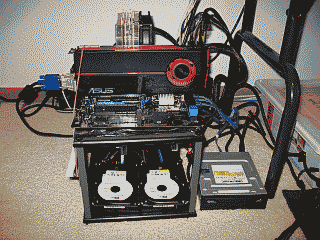
I like to build systems outside of the case. Then, when I’m sure everything is running well, I’ll place the components in the case and dress up the wiring (See Figure 1). Similar to other motherboard manufacturers, Intel has finally taken to mounting the SATA II ports horizontally, facing the back of the case, instead of vertically. Good thing too because the video card would likely have prevented me from using the first couple of ports. I’m using two 36GB Western Digital “Raptor” drives configured for Raid 0 to hold the OS. I placed these on SATA ports 0 & 1. I also have a pair of 74 GB Raptors will be configured for Raid 0, but these will become my d:\ drive and hold only data files. I placed these drives on SATA ports 2 & 3. My CD/DVD drive then ends up on port 5.

 Screenshot of my Core i7 build outside of the computer case

Figure 1

I decided to get a new power supply for this rig. The existing PC Power & Cooling Silencer 750 that I originally intended to use for this upgrade I felt could best be used elsewhere. I’m partial to the single 12 VDC rail design for PC power supplies so I ended up picking up Corsair’s’s 750TX.

Intel offers several methods for updating their BIOS, including updating directly from the OS using a utility called “Express BIOS Update.” Sans OS though, your choice is to use Intel’s tried and true “IFLASH2” utility and the BIOS file from a bootable floppy, USB or optical disk, or use a bootable ISO image to update the BIOS firmware. I chose the latter and it was a breeze. Burn the image to a CD-R, boot to it, and in 5 minutes your BIOS firmware is updated.

In order to build the RAID arrays, I navigated to Advanced -> Drive Configuration -> Configure SATA and made sure that the RAID option was selected, then rebooted and entered Intel’s Raid configuration utility (using CTRL-l). I chose the default stripe size of 128 KB for my two RAID 0 arrays. Returning to the BIOS, I made some additional preliminary tweaks before installing the OS, including disabling the 1394 port (never use it), disabling CPU and System fan control (I prefer to run them wide open), and turning off the Event Log (this is a feature?). Adjustments to Performance section of the BIOS will be saved for when I start overclocking the system. I then booted into Memtest86+ (v4.00) and ran it for 2-3 passes to verify that the RAM was solid. Sweet, no errors.

Windows 7 comes with native support for RAID, so rather than choosing to install my own via the usual “F6” method I let Windows use its own. After the OS was fully operational though, I installed Intel’s RAID driver, as well as the essential audio, LAN and graphics drivers; activated the OS and downloaded Microsoft updates. I then installed applications and performed the my usual OS performance tweaks. With the exception of a few applications, such as Guild Wars and Quake 3 Arena, which I made run using compatibility mode, all my applications installed and ran just fine on Windows 7 Pro 64-bit.

My Canon i560 printer had me scratching my head though. First, Canon’s Windows 7 64-bit driver for the i560 does not work; and, to complicate things, my printer is parked on a D-link print server. To install a driver that would allow this PC to see the printer, I first had to connect the printer directly to the PC via USB. Then, instead of messing further with the flaky Canon driver, I let Win 7 find and use its own native driver. Then I deleted that printer and put the printer back on the print server. I created a new printer, but this time configured for a proper TCP/IP port. When it came time to load a driver, I simply reused the one Win 7 added when the printer was directly connected.

The Temp

Almost immediately after I get a new system up and running on the bench I navigate to the BIOS’s hardware monitor to verify the temperature(s) it’s reporting for the CPU so as to ensure I have the heatsink and fan installed and working correctly.

Back in the good old days (you know, before Core i7), you would typically pay attention to the “CPU temperature” the motherboard was reporting. This is the processor’s Tcase temperature, the temperature at the geometric center of the topside of the integrated heat spreader as measured (or estimated) by a sensor IC. This temperature value is routinely used by utilities such as Everest, SpeedFan, as well as ones provided by the motherboard manufacture, to report the thermal condition of the processor. According to Intel, Tcase should be maintained at or below the thermal threshold listed in the processor’s datasheet. For the Core i7 860 processor for example, that value is 72.7C. Given a reasonably accurate measurement of Tcase and the not-to-exceed threshold value provided by Intel, you knew exactly where you stood with respect to your processor’s temperature.

Enter core temperatures. Unlike Tcase, the processor’s core temperature is the temperature measured by the processor’s Digital Thermal Sensor (DTS). This value is always relative to what Intel feels is the maximum core temperature threshold for a given processor model, a parameter Intel calls TjMax. Nominal core temperature values, as reported by utilities such as Core Temp and Real Temp, would be an equally reliable way of representing processor temperature if you knew with certainty the value of TjMax. Knowing that value would provide you with a fairly reliable way to calculate your core temperature, and by extension, how much margin you have before encountering TjMax:

Core Temperature = TjMax – DTS reading

Unfortunately, Intel treats the TjMax value as if it were a matter of national security, and so these utilities are left to essentially guess what the TjMax value is in order to report the nominal core temperature values. In other words, core temperatures, while nice to know, aren’t terribly useful because: 1) Their accuracy is suspect; and 2) there is no direct correlation to the nominal value of Tcase and it’s threshold as provided by Intel in the processor’s specification.

On the Intel DP55KG that I’m using for this upgrade, the situation seems to have gotten even murkier. On this motherboard there are two temperature readings reported in BIOS: Internal and Remote. Instead of Tcase, this Internal temperature is apparently meant to represent the processor’s core temperatures. This was confirmed when, after installing Real Temp, the temperatures reported by that utility matched the one reported by the BIOS within about one degree. Speedfan’s readings also closely matched these readings. And the “Remote” temperature reported by the BIOS? Since it routinely reports temperatures 2-5 degrees below those reported by the Internal reading, I suspect its readings come from a thermal sensor near the processor, whose job it is presumably to keep track of the internal case temperature.

It appears then that Intel now seems to be more interested in focusing on core temperatures and their relative difference from TjMax. But how does this help me ascertain how much headroom I have with respect to the Core i7 860’s thermal profile value of 72.7C? In short, it doesn’t. So I guess I’ll need to trust that Intel will keep the processor from exceeding whatever it feels are its critical thermal thresholds, Tcase or otherwise. My job, it appears, is merely to keep the core temperatures as low as possible.

The DP55KG’s BIOS was reporting that the processor’s core temperature was idling at ~36C (ambient room temperature is routinely ~20C). I felt I could probably do better than this so I went in search of a heatsink to replace the Arctic Cooling Freezer 7 Rev.2 I was using for this build. As mentioned in my initial post, even finding a suitable heatsink for an LGA1156 CPU was a challenge. While there were plenty of options for 1366-based boards at the time I was pulling the parts together for this build, very few of the more reputable heatsink manufactures had yet to put out parts made specifically for with newer LGA1156. The second time out though I ran into a Maximum PC article regarding the Cooler Master Hyper 212 Plus air cooler.

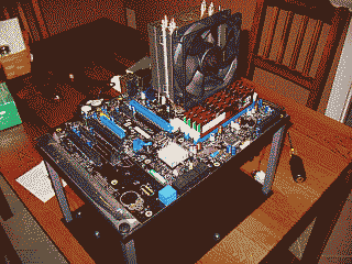
I picked one up, replaced the Freezer 7, and was able to lower the idle temperature to 30C. Needless to say I’m quite happy with it. As you can see though, the heatsink does land very close to the RAM modules (See Figure 2).

 Screenshot of proximity of the heatsink to the RAM

Figure 2

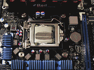
This brings up another issue that would be a good to mention here and that’s the best procedure I found for applying the thermal compound. Arctic Silver suggests applying their Arctic Silver 5 product in a line over the CPU heatspreader horizontally, but not spread the line out. Instead, when you place the heatsink on top of heatspreader of the CPU, the line of Arctic Silver 5, they suggest, will “spread out just like an oval pancake.” Well, it did spread out a bit and it may resemble an oval pancake (See Figure 3), but this method does not yield the best results. I tried several variations of this pancake method and compared the results with the more traditional method of placing a small amount of compound in the center of the processor and spreading it thinly and evenly so it covers the entire top of the processor, and in each case the latter method produced the best results.

 Screenshot of the Core i7 860 and the result of applying a thin horizontal line of thermal compound

Figure 3

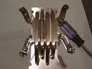
I think the problem with Arctic Silver’s method is that it actually places too much compound on the processor resulting in poorer heat transfer, not better. But perhaps a more significant factor leading to poorer results in my case is the unique design of the Cooler Master 212’s heatsink itself. Instead of the typical smooth copper surface, this heatsink is built in such a way as to allow its heat pipes to rest directly on the processor. Consequently, the heatsink surface is not smooth but instead has ridges where the heat pipes nestle against a nickel plate. These ridges seem to be preventing the thermal compound from spreading out as well as Arctic Silver intended (See Figure 4).

 Screenshot of the Core i7 860 and the result of applying a thin horizontal line of thermal compound

Figure 4

Final Thoughts

After putting each of these speed bumps behind me I was ready to place all of the components in the NZXT Tempest mid tower case. I decided to forego using the case’s side fan in order to improve positive air flow, but even with one less fan, it was immediately apparent that I was going to run out of fan headers. No worries though, I typically run the fans wide open anyway so I simply wired 12VDC to each of them. The Tempest isn’t the easiest case to dress up wiring in but I managed hide some of it behind the motherboard (See Figure 5).

 Screenshot of the Core i7 860 and the result of applying a thin horizontal line of thermal compound

Figure 5

In the next post I’ll share my experiences with overclocking the DP55KG and Core i7 860.

iceflatline