bookmark_borderHow to Assign Static IP Addresses to OpenVPN Clients in pfSense

(20180407 – The steps in this post were amended to address changes in recent versions of software — iceflatline)

This post describes how to configure the OpenVPN server in pfSense to assign static IP addresses to its remote access client hosts.

pfSense (i.e., “making sense of packet filtering”) is a customized version of FreeBSD tailored specifically for use as a perimeter firewall and router, and can be managed entirely from a web-based or command line interface. In addition to being a firewall and routing platform, pfSense includes a long list of other features, as well as a package system allowing its capabilities to be expanded even further. pfSense is free, open source software distributed under the BSD license.

OpenVPN is a lightweight VPN software application supporting both remote access and site-to-site VPN configurations. It uses SSL/TLS security for encryption and is capable of traversing network address translation devices and firewalls. The OpenVPN community edition is free, open source software and portable to most major operating systems, including Linux, Windows 2000/XP/Vista/7, OpenBSD, FreeBSD, NetBSD, Mac OS X, and Solaris. It is distributed under the GPL license version 2.

All steps involved assume that pfSense and its OpenVPN server are installed and operating correctly. The versions for the software used in this post were as follows:

  • pfSense 2.4.3

Let’s get started…

Log into pfSense’ “webConfigurator” interface and navigate to VPN->OpenVPN. Select the icon to edit the server and ensure that the value for “Topology” under “Client Settings” is set to “net30 – Isolated /30 network per client”, then select “Save”.

Now connect to your pfSense firewall using SSH and open /var/etc/openvpn/server1.conf. Ensure that this configuration file contains the following line pointing to a valid directory for containing OpenVPN client host configuration files. The default directory in pfSense for this purpose is /var/etc/openvpn-csc/server1. You can change this directory if you wish but for our example we’ll retain the default:

In this directory we will create a file for each remote access client host we want the OpenVPN server to assign a static IP address to. The file name of each file must be the same name as the client host’s OpenVPN SSL certificate. For example, if you would like to configure a static IP for a client host with the certificate name “bob” then create the following file:

Open this newly created file and add the following line, which contains a pair of IP addresses from the IPv4 virtual network you’ve configured for private communications between the OpenVPN server and your client hosts. Note that you cannot use just any pair of addresses from within this subnet. Each pair of ifconfig-push addresses represent the OpenVPN client and server IP endpoints. They must be taken from successive /30 subnets in order to be compatible with Windows client hosts and the TAP-Windows driver. Specifically, the last octet in the IP address of each endpoint pair must be taken from set defined in the “Configuring client-specific rules and access policies” section of the OpenVPN HOWTO. In this example, our OpenVPN server is using the virtual network 192.168.20.0/24 and we’ve chosen an appropriate pair of endpoint addresses to use from this subnet. Note that the first IP address in following line is the IP address assigned to the client host, the second is the address the server uses:

Once you’ve added this line to /var/etc/openvpn-csc/server1/bob you’ll need to restart the OpenVPN server in pfSense. You can do this from Status->Services in the pfSense “webConfigurator” interface.

Note that any files added to /var/etc/openvpn-csc/server1 will be deleted by the system if it reboots. To protect these files you can use the chflags utility to set the system immutable flag on the file. Once this flag is set, no one can delete or modify file, including root. You must be the root user to set or clear the immutable flag:

To verify that the immutable flag has been set:

Output:

To clear the immutable flag:

Conclusion

There you have it. Some minor configuration of your pfSense machine and its OpenVPN server will start assigning static IP addresses to the remote access client hosts you designate.

References

http://openvpn.net/index.php/open-source/documentation/howto.html

bookmark_borderHow To Create And Configure VLANs In pfSense

(20171231 — The steps in this post were amended to address changes in recent versions of software. Minor editorial corrections were also made — iceflatline)

pfSense is a customized version of FreeBSD tailored specifically for use as a perimeter firewall and router, managed entirely from a web browser or command line interface. pfSense includes a long list of other features, as well as a package system allowing its capabilities to be expanded even further. pfSense is free, open source software distributed under the BSD license.

A VLAN (“Virtual Local Area Network”) is a logical grouping of network hosts (and other resources) connected to administratively defined ports on a switch. This enables hosts to communicate as if the attached to the same physical medium, when in fact they may actually be located on different LAN segments. A VLAN is treated like its own subnet or broadcast domain, which means that Ethernet frames broadcast onto the network are only switched between the ports logically grouped within the same VLAN.

In this post I will describe how to create and configure a VLAN in pfSense. Once configured, you’ll be able to route (or prevent routing) traffic between this VLAN and other VLANs, and each VLAN will be able to share the same Internet connection. To help explain the steps involved, we’ll create a static VLAN on a 24-port switch and trunk that VLAN from the switch to the LAN interface on pfSense, where we will assign the VLAN a unique /24 private IP subnet.

All steps involved assume that: 1) pfSense is installed correctly and providing basic Internet connectivity to an existing LAN interface; 2) the NIC (“Network Interface Controller”) assigned to the LAN interface supports IEEE 802.1Q VLAN tagging; and, 3) the switch connected to the LAN interface is capable of supporting the creation, configuration and trunking of port-based VLANs.

The software versions used in this post were as follows:

  • 2.4.2-RELEASE-p1 (amd64)

The switch used in this post was a Cisco model SG200-26; a so-called “smart switch,” featuring, among other things, Gigabit Ethernet, a web-based management interface, and simultaneous support for up to 256 port-based and IEEE 802.1Q tag-based VLANs.

Each switch, and its associated management interface is different; therefore, you’ll need to make the appropriate adjustments when following the instructions in this post in order to successfully configure your particular switch.

Let’s get started…

Configuring the Switch

As you may recall, static VLANs, often referred to as “port-based” VLANs, are created by assigning switch ports to a preconfigured VLAN identifier. In this example, we’ll configure a static VLAN on our switch and assign it VLAN ID 50. Note that you can use any positive integer between 2 and 4094 you’d like for your VLAN ID, however, VLAN IDs 1 and 4095 should be avoided because, as a general rule, most switches by default assign all ports to VLAN ID 1, the “administrative” VLAN ID, and VLAN ID 4095 as the “discard” VLAN.

Begin by navigating to VLAN Management->Create VLAN and select “Add.” Enter a value of 50 in the “VLAN ID” field and enter a name to denote this particular VLAN in the “VLAN Name” field. In this example, we’ve used the name “vlan50.” When complete, select “Apply”. (See Figure 1)
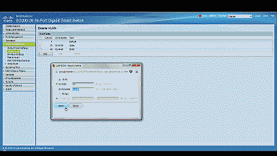
Screenshot showing the creation of a new VLAN ID 50 in the Cisco SG200-26 switch

Figure 1

Before assigning membership of a particular port to our new VLAN, we must first configure that port to be either an “Access” port or a “Trunk” port. Access ports are ports that are members of only one VLAN. This type of port is normally used for attaching end devices which are generally unaware of a VLAN membership, either because their NIC is incapable of tagging Ethernet frames a VLAN ID, or they are not configured to do so. Switch ports configured as Access ports remove any VLAN information from the Ethernet frame before it is sent to the device. Trunk ports on the other hand can carry multiple VLAN traffic, and are normally used to connect switches to other switches or to routers. It is very often the case that small-business grade switches, such as the Cisco SG200, designate each port as a Trunk port by default.

To keep our example simple, we’ll assume that the device(s) connected to the switch are not configured, or are unable to be configured, to tag Ethernet frames with a VLAN ID. Consequently, in this example, we’ll configure port 19 as an Access port, and assign it membership in our newly created VLAN. Furthermore, we’ll also assume that port 25 is currently being used to connect the switch to the pfSense LAN interface, and configure it as a Trunk port, assigning it membership in our newly created VLAN.

Navigate to VLAN Management->Interference Settings, select port 19 and then select “Edit”. Change the Interface VLAN Mode from Trunk to Access, then select “Apply” (See Figure 2). Now follow similar steps to configure port 2 as an Access port.
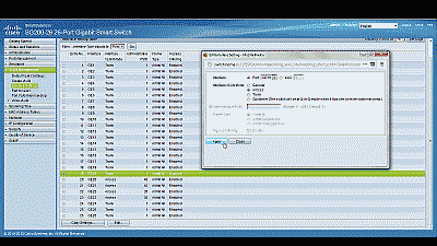
Screenshot showing port 19 being configured as an Access port in the Cisco SG200-26 switch

Figure 2

Next, navigate to VLAN Management->Port VLAN Membership, select port 19 and then select “Join VLAN”. Since Access ports can be added as untagged to only a single VLAN, we’ll need to first remove the default VLAN the switch automatically assigns to each port (usually VLAN 1). Highlight VLAN 1 by left-clicking on it, then select the arrow icon to remove it from the interface. Now highlight VLAN 50 by left-clicking on it, then select the arrow icon to add it to the interface, ensuring that “Untagged” is selected from among the options under “Tagging”. Select “Apply” when completed (See Figure 3).
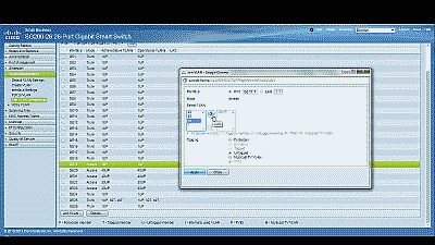
Screenshot showing port 19 being joined to VLAN 50 in the Cisco SG200-26 switch

Figure 3

With switch port 19 configured as an Access port and joined to VLAN 50 any Ethernet frames that enter that port will be tagged with the appropriate VLAN ID. Now let’s configure the port 25, the port that is connected to the LAN NIC in pfSense. This port will be configured as a Trunk port and joined to VLAN 50 so that, in addition to passing the Ethernet frames from from devices attached to the other ports on the switch to pfSense, it will also pass Ethernet frames tagged with VLAN ID 50 entering switch port 19.

Ensure that port 25 is configure as a Trunk port, then navigate to VLAN Management->Port VLAN Membership, select port 25 and then select “Join VLAN”. Highlight VLAN 50 by left-clicking on it, then select the arrow icon to add it to the interface, ensuring that “Tagged” is selected from among the options under “Tagging”. Select “Apply” when completed (See Figure 4).
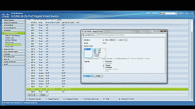
Screenshot showing port 25 being joined to VLAN 50 in the Cisco SG200-26 switch

Figure 4

That’s it for configuring the switch. If your switch supports both a running configuration and a startup configuration, make sure to save the changes you’ve made to the startup configuration so that they are not lost should the switch reboot for any reason.

Configuring pfSense

Now we need to create and configure VLAN 50 in pfSense. Navigate to Interfaces->Assignments and make note of the device driver name assigned to the LAN NIC. For this example we’ll assume the device driver name is “em1” (See Figure 5). The LAN interface will serve as the “parent interface” for the VLAN interfaces we will create in the next step.
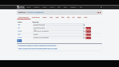
Screenshot showing the device driver name assigned to the LAN NIC in pfSense

Figure 5

Next, navigate to Inerfaces->Assignments->VLANs and select the “+ Add” icon. In the subsequent screen, select “em1”, the LAN NIC interface, from among the options in the drop down list under “Parent interface”, and enter the value of 50 under “VLAN tag”. Add an optional description for this VLAN under “Description”, then select “Save” (See Figure 6).
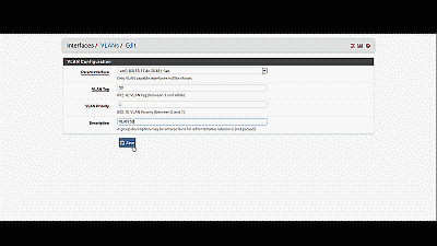
Screenshot showing the configuration of a VLAN interface in pfSense

Figure 6

After creating the VLAN interface, return to Interfaces->Assignments and select the “+ Add” icon to add the “VLAN 50 on em1-lan (VLAN 50)”, then select “Save” (See Figure 7). At this point you’ll notice that under the “Interface” column pfSense has likely denoted VLAN 50 as an optional or “OPT” interface. Don’t worry, we’ll address that next.
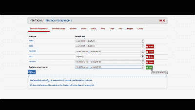
Screenshot showing the addition of a VLAN interface in pfSense

Figure 7

For this example we’ll assume that pfSense has assigned VLAN 50 as OPT4. Navigate to Interfaces->OPT4 and select “Enable Interface”. Under “Description” replace “OPT4” with “VLAN 50”, then select “Static IPv4” from among the options in the drop down list under “IPv4 Configuration Type”. We’ll use network 192.168.50.0/24 for VLAN 50 by assigning the static IP address 192.168.50.1 on this interface, and selecting the network mask of “24” under the “Static IP Configuration” section. The other parameters can remain at their default values. Select “Save” and “Apply changes” when complete (See Figure 8). Now if you navigating back to Interfaces->Assigments you will see VLAN 50 listed and labeled with the description you added when enabling the interface in the previous steps.
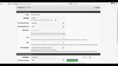
Screenshot showing the VLAN 50 interface being enabled in pfSense

Figure 8

Next, we need to build a firewall rule for our two new VLANs so that traffic can pass to / from the WAN interface, and by extension, to the Internet. Navigate to Firewall->Rules and select the VLAN 50. Select the “Add” icon (there are currently no rules so either Add icon will work) to create a new rule. For our example, we’ll build a simple outbound pass rule for any protocol in VLAN 50, similar to the way a typical LAN outbound pass rule would be configured. Select “any” from among the options in the drop down list Under “Protocol”, and under “Source” select “VLAN50 net” from among the options in the drop list. If desired, you may enter a description of this newly created rule for your reference under “Extra Options”. The other parameters can remain at their default values. Select “Save” and “Apply changes” when complete (See Figure 9).
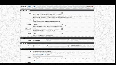
Screenshot showing the creation of a firewall rule for VLAN 50 in pfSense

Figure 9

Unless you plan to assign static IP addresses to host devices, you’ll want to configure a DHCP server for the new VLAN 50. Navigate to Services->DHCP server and select VLAN 50. Select “Enable DHCP server on VLAN50 interface”, then enter the range of IP addresses within the network 192.168.50.0/24 you’d like the DHCP server to use under “Range”. Finally, pfSense will use the IP address assigned to this interface as the gateway address by default. For our example this address will be 192.168.50.1. If your requirements call for something different, enter an IP address for the network gateway under “Gateway”. The other parameters can remain at their default values. Select “Save” when complete (See Figure 10).
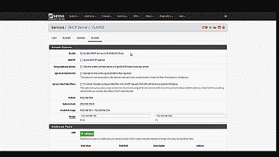
Screenshot showing the creation and configuration of a DHCP server for VLAN 50 in pfSense

Figure 10

You’ll also want to navigate to Services->DNS Forwarder->Interfaces and ensure that interfaces used by the DNS Forwarder for responding to queries from clients includes VLAN50, then select “Save” and “Apply changes” when complete (See Figure 11).
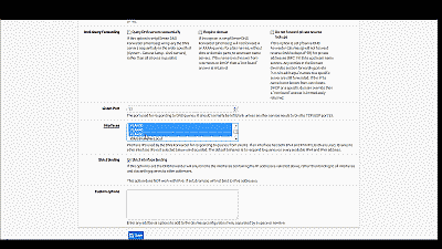
Screenshot showing the inclusion of the VLAN 50 interface in the DNS Forwarder in pfSense

Figure 11

Wrapping up

At this point the LAN switch and pfSense should be configured to support VLAN 50. To test, connect a host device such as a desktop or laptop computer to port 19 on the switch. If you’ve configured everything as described, you should receive an IP address within the DHCP address range you’ve specified for VLAN 50 network 192.168.50.0/24. The default gateway, DHCP server and DNS server addresses should be 192.168.50.1. You should also have Internet connectivity.

Be aware that as currently configured, each VLAN is routed to all other VLANs. If you would like to disallow some or all traffic to/from a particular VLAN you must create firewall rules explicitly stating what traffic should not be routed. Keep in mind that pfSense evaluates firewall rules on a first-match basis (i.e. the action of the first rule to match a packet will be executed). So, for example, if you wanted to block all VLAN 50 traffic from reaching the LAN you might create a rule to that effect before the one we created previously to route all VLAN 50 traffic to any destination (See Figure 12).
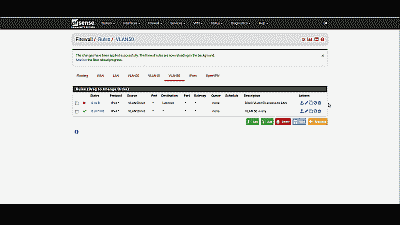
Screenshot showing the placement of a firewall rule blocking all traffic in VLAN 50 from reaching the LAN in pfSense

Figure 12

Conclusion

VLAN support in pfSense is not hard to configure nor complicated to manage, assuming your switch and NICs support this capability. To help explain the steps involved, we created a static VLAN on a commodity 24-port small-business switch and trunked that VLAN to the LAN interface on pfSense. We then created and added the VLAN interface, created the requisite firewall rules, and assigned the VLAN a unique /24 private IP subnet with host addressing handled using DHCP. The VLAN is able to share the pfSense’s Internet connection and we are able further configure pfSense to prevent routing traffic between each VLAN, if desired.

bookmark_borderHow To Access Your VirtualBox Guest VM From The Host Using SSH

(20180430 — The steps in this post were amended to address changes in recent versions of software — iceflatline)

Recently I had the occasion to spin up a Ubuntu server Virtual Machine (“VM”) in VirtualBox on a Windows-based host machine. Those of you who have performed a similar excercise know that the default window size that VirtualBox provides to command-line-based VMs, like *BSD and Ubuntu server, etc., is rather small, somewhere in neighborhood of the standard VGA resolution of 640 x 480 pixels. Normally the fix for this, of course, would be to install what VirtualBox calls “Guest Additions,” which consists of device drivers and other applications that optimize the guest operating system for, among other things, the ability to enlarge the window size. However, getting Guest Additions to install and run properly on command-line-based guest VMs is a monumental pain in the ass. One work-around that seems to work fairly well is to switch the VM window to “scale mode” (View->Switch to Scale Mode or Host+C), resulting in what is essentially a magnified version of the window and its contents. An even better solution, in my opinion, is to configure the VM so that you can connect to it directly from the host machine using Secure Shell (“SSH”), giving you full control over the window and text size of the guest VM.

This post explains how to access a VirtualBox Ubuntu server guest VM from the VirtualBox host machine using SSH. It then goes on to explain how to accomplish the same task when using a FreeBSD guest VM. The software versions used in this post were as follows:

  • FreeBSD 11.0-RELEASE
  • Ubuntu Server 18.04 LTS
  • VirtualBox 5.2.6

Let’s get started…

First, let’s add a new “VirtualBox Host-Only Ethernet Adapter” in VirtualBox. This new adaptor will allow us to enable a private network consisting of our host machine and our guest VM. The host can connect to any guest VMs configured to use this adaptor, and they can connect to each other, but nothing outside of this virtual network will be permitted access.

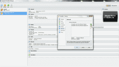
Navigate to Files->Preferences->Network and click on the “+” icon to add new adaptor. You’ll see that VirtualBox creates a new adaptor called “VirtualBox Host-Only Ethernet Adapter #2” (See Figure 1).

Screenshot showing the creation of a VirtualBox Host-Only Ethernet Adapter in VirtualBox

Figure 1

Right now you might be thinking “but couldn’t I just use the existing default VirtualBox Host-Only Ethernet Adaptor?” You absolutely could; however, setting up a second one allows you to customize it to your liking, leaving the default adaptor in its default configuration as a fallback.

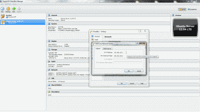
Now, double-click the new adaptor (or highlight it and select the edit icon) and note the IP address and subnet mask (e.g., 192.168.135.1 and 255.255.255.0) that VirtualBox has arbitrarily assigned under the “Adapter” tab. You may change these network parameters if desired, however, it is preferable to retain “1” as the value of the last octet in the IP address (See Figure 2).

Screenshot showing the IP address and subnet mask assignment in the VirtualBox Host-Only Ethernet Adapter #2

Figure 2

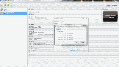
Optionally, you may configure a DHCP server on the VirtualBox Host-Only Ethernet Adapter #2 so that the guest VM obtains an IP address automatically at boot time. This can be accomplished by navigating to Files->Preferences->Network, double-clicking the new adaptor (or highlighting it and selecting the edit icon), selecting the “DHCP Server” tab and the selecting “Enable Server”. You’ll then need to modify the various DHCP server parameters (e.g., Server Address, Server Mask, etc.), keeping in mind that they should encompass the IP address configured for the adaptor, else the IP address should be modified so that it lies within the DHCP server parameters you’ve configured. When finished, select “OK” (See Figure 3). Note: I typically forgo using the DHCP server, electing instead to use a static IP address. That way, I can consistently use the same address each time I want use SSH to connect to the guest VM.

Screenshot showing the DHCP server configuration tab in the VirtualBox Host-Only Ethernet Adapter #2

Figure 3

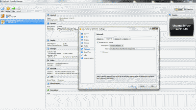
Let’s configure our Ubuntu server VM so that it will use the new VirtualBox Host-Only Ethernet Adapter #2. Shutdown the Ubuntu server VM if it’s running. Right-click on the VM and select Settings->Network. Select the “Adapter 2” tab, then select “Enable Network Adapter”. From among the options under “Attach to:”, select “Host-Only Adapter”, then select “VirtualBox Host-Only Ethernet Adapter #2” from among the options under “name:”. Now select “OK” (See Figure 4).

Screenshot showing the selection of VirtualBox Host-Only Ethernet Adapter #2 for use by the Ubuntu server virtual machine

Figure 4

Now start the Ubuntu server VM. After the system has fully booted, login to the VM at the VirtualBox console window and execute the command ifconfig -a to list all network devices. In addition to your primary network device, enp0s3 (in this example), you should now see a second network device listed, enp0s8 (in this example). If you chose to setup a DHCP server when creating VirtualBox Host-Only Ethernet Adapter #2, then enp0s8 should already have an IP address assigned to it from among the pool of addresses you chose to use with setting up the DHCP server, in which case you should make a note of this address and use it to connect to the Ubuntu server VM using SSH.

If you elected not to setup a DHCP server when creating VirtualBox Host-Only Ethernet Adapter #2, then you’ll need to assign a static IP address to network device enp0s8. First, install the package ifupdown:

Then open /etc/network/interfaces as the root user and add the following lines, making sure to change the values shown in this example so that they fall within the IP subnet parameters chosen when creating the new VirtualBox Host-Only Ethernet Adapter #2:

Now start the interface so that it obtains the new network parameters:

At this point you should be able to connect to the Ubuntu server VM via SSH using this static IP address.

FreeBSD Guest VM

A similar approach can be taken for a FreeBSD guest VM. The setup and configuration of the VirtualBox Host-Only Ethernet Adapter in VirtualBox is identical to what has been described thus far for the Ubuntu server VM. However, in order to assign a static IP address to the new network interface, em1 in the case of FreeBSD, you’ll need to open /etc/rc.conf as the root user and add the following line, making sure to change the values shown in this example so that they fall within the IP subnet parameters chosen when creating the new VirtualBox Host-Only Ethernet Adapter #2:

Then restart the interface so that it obtains the new network parameters:

Conclusion

The default window size that VirtualBox provides to command-line-based guest VMs like BSD and Ubuntu servers is typically very small, resulting in a poor user experience for those administrators trying to perform work beyond just a few quick simple commands. Fortunately, VirtualBox can be configured so that the user can connect directly to a guest VM from the host machine using SSH, giving the user full control over window and text sizing.

bookmark_borderHow to Securely Login to Your WordPress Web Site Using SSH Port Forwarding

This post describes how to securely login to your web site using an SSH (“Secure Shell”) tunnel created using dynamic SSH port forwarding. You will need to have access to an SSH connection to your web hosting account. Most web hosts should be able to provide you with one. While this post uses a WordPress-based web site as an example, the techniques described should be able to be applied to any web site so long as the web host permits SSH connections.

Introduction

A SSH tunnel consists of an encrypted data path created through a SSH protocol connection. A SSH tunnel can be used to transfer unencrypted traffic over an IP network, such as the public Internet, through an encrypted channel. Why use an SSH tunnel to login into your WordPress web site? In brief, better security. Unless you already have SSL configured on the server and have WordPress correctly configured to force SSL logins, your login name and password are passed in the clear each time you login to administer the site. Dynamic SSH port forwarding transforms the SSH client on a local machine into a SOCKS proxy server. Any traffic sent to the proxy will be sent to the SSH server, which will forward that traffic as its own firewall and routing rules permit. We can use this capability to our advantage to forward login credentials over the SSH connection to WordPress more securely.

To set up an SSH tunnel using dynamic SSH port forwarding, a port number is chosen for use as the SOCKS server port. Whenever a connection is made to this port, all traffic is forwarded to the SSH server, and the application protocol is then used to determine where to connect to from the SSH server. In our case that protocol is HTTP and our web browser must be configured specifically to use the proxy server (and must reconfigured when you stop using the proxy server). For purposes of example, we’ll use the standards SOCKS port 1080 (technically, you can use any port number, however be aware that some programs will only work if you use 1080), and Firefox as the web browser, and we’ll assume that the web host’s SSH server is listening for incoming connections on the SSH default port 22.

Dynamic Port Forwarding On Linux/Unix

Creating a SSH tunnel using dynamic port forwarding on a Linux/Unix system is quite easy. Simply start a termnal session and enter the following command:

The -D option specifies a local “dynamic” application-level port forwarding and the port parameter is the port chosen for the proxy server to listen on. The user@hostname parameter is the remote SSH server and associated account where you will forward your connection. In our case user will typically be your web host account user name and hostname will typically be your web site’s domain name. For example:

If your web host’s SSH server is listening for connections a port other than 22 then you can specify the correct port in the command using the -p option, for example:

If this is the first time you’ve attempted to connect to your web host provider using SSH, you’ll likely receive a warning concerning the authenticity of the host you’re trying to reach along with a fingerprint of its public key and asked if you’re sure you want to continue connecting. If you’re absolutely sure that you’re indeed connecting to your host provider, accept by entering Yes. You’re then typically requested to enter your account password and the connection will proceed. The command prompt should be returned to you without error indicating that tunnel was established successfully.

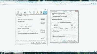
Now open Firefox and navigate to Tools->Options->Advanced->Network and select “Settings” (Note: in some implementations of Firefox, particularly on Linux, network connection settings are found under Edit->Preferences->Advanced->Network). Select “Manual proxy configuration” and enter localhost in the “SOCKS Host:” field and 1080 in the associated “Port” field, then select “OK” and once again in the Options menu to close it out. (See Figure 1).

Screenshot of the Firefox network settings with manual proxy configuration

Figure 1

Now simply point your browser to your WordPress login URL – usually your-web-site-url/wp-admin or your-web-site-url/wp-login.php – where you can login securely over your newly created SSH tunnel to administer the site. Note that you must maintain the SSH connection in order to maintain your connection to the web site. When finished using the tunnel, simply exit the terminal session that is maintaining the SSH connection and return Firefox to its default “no proxy’ settings.

Dynamic Port Forwarding On Windows

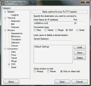
Creating an SSH tunnel using dynamic port forwarding on a Windows system is also easy; however, we’ll first need to download and install an SSH application (Windows doesn’t support SSH natively). There are several out there to choose from, but the one I typically use is PuTTY, a free implementation of Telnet and SSH for Win32 and Linux/Unix platforms. Download PuTTY.exe (or the Installer version if you’d prefer) and run it. Enter your web site domain name in the “Host Name (or IP address)” field. If your web host’s SSH server is listening for connections a port other than 22 then modify the “port” field to reflect the correct port number (See Figure 2).

Screenshot of the PuTTY application

Figure 2

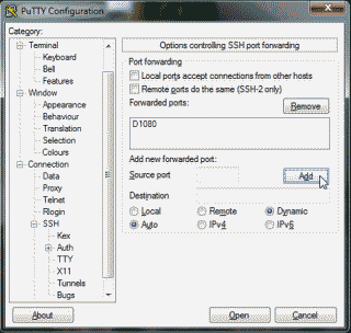
Next, under the “Category” column on the left side of the application, navigate to Connection->SSH->Tunnels. Enter 1080 in the “Source port” field and select the “Dynamic” radio button, then select “Add” (See Figure 3).

Screenshot of where to create a dynamic SSH tunnel in the PuTTY application

Figure 3

Now select “Open” to initiate the connection. If this is the first time you’ve attempted to connect to your web host provider using SSH, you’ll likely receive a popup from the PuTTY application with a warning concerning the authenticity of the host you’re trying to reach along with a fingerprint of its public key. If you’re absolutely sure that you are indeed connecting to your host provider, select “Yes” to add the public key to PuTTY’s cache and carry on connecting. Alternatively, if want to connect just once, without adding the key to the cache, select “No”. You’re then typically requested to enter your account password and the connection will proceed. The command prompt should be returned to you without error indicating that tunnel was established successfully.

Now open Firefox and configure the settings as described above in the Linux section. When complete, point your browser to your WordPress login URL where you can login securely over your newly created SSH tunnel to administer the site. Note that you must maintain the SSH connection (i.e., the PuTTY window must remain open) in order to maintain your connection to the web site. When finished using the tunnel, simply exit the terminal session that PuTTY created for the SSH connection and return Firefox to its default no proxy settings.

Conclusion
Well, there you have it. Would obtaining an SSL certificate be simplier? Perhaps. But until you do here’s a way to login more securely to your WordPress web site using an SSH tunnel created using dynamic SSH port forwarding.

References

Lucas, M. SSH Mastery. USA: Tilted Windmill Press, 2012. Print.

bookmark_borderHow to use Clonezilla to Create and Backup Disk Images to FreeNAS

FreeNAS is an open source storage platform based on FreeBSD that supports file sharing across Windows, Apple, and Unix/Linux systems. Clonezilla is an open source clone utility for doing bare-metal backup and recovery for disks and disk partitions.

In this post I will describe how to use Clonezilla to create image files of disks or disk partitions and backup those images in real time over a network to a machine running FreeNAS. All steps involved assume you have a running implementation of FreeNAS. The software versions used in this post were as follows:

  • Clonezilla v1.2.12-10
  • FreeNAS v0.7.1 Shere (revision 5127)

Configure FreeNAS

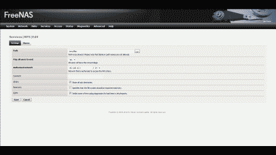
Let’s start by making a new directory in FreeNAS to hold the images we create using Clonezilla. For the purpose of example, let’s assume there is an existing mount point located at /mnt/files and create a new subdirectory called images at that location. Next, let’s enable Network File System (“NFS”) service in FreeNAS so that /mnt/files/images can be accessed from Clonezilla. Login into the FreeNAS web interface and navigate to Services -> NFS -> Settings and make sure that the check box for enabling NFS is checked then specify the number of servers that will run (Hint: the default value of four should easily handle dozens of users). Now select “Save and Restart.” Next, navigate to Services -> NFS -> Shares and select the “+” icon, where you are presented with the configuration screen for creating a new NFS share. Enter the path to be shared; the network that is authorized to access /mnt/files/images; and, make sure that the “All dirs” and “Quiet” check boxes are selected. The remaining options can remain at their defaults (See Figure 1). Then select “Add” then “Apply changes” (Note: If you would prefer to use Common Internet File System (“CIFS”) instead of NFS, navigate to Services -> CIFS/SMB and select the appropriate settings and add your network share).

Screenshot of NFS shared path configuration in FreeNAS

Figure 1

Using Clonezilla
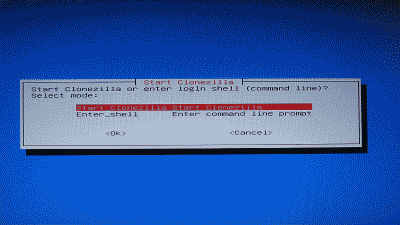
Now it’s time to use Clonezilla. Download a copy of Clonezilla live and burn it to a CD (or place it on a bootable USB drive). Boot the system using the Clonezilla live disk, where you’ll be given the option to change the language and select an alternative keyboard keymap, eventually arriving at the “Start Clonezilla” Screen (See Figure 2).

Screenshot of Clonezilla's start screen

Figure 2

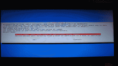
Highlight “Start Clonezilla” and select “Ok.” The screen that follows provides a choice of cloning/restoring a disk or disk partition using using an image, or cloning/restoring a disk or disk partition directly to another disk or disk partition. Since we’ll be creating an image of a disk, we should select “device-image work with disks or partitions using images” (See Figure 3).

Screenshot of Clonezilla menu option to work with with images or devices when cloning or restoring

Figure 3

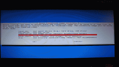
Next, Clonezilla will ask us to define where the image will be saved to (or read from), providing you with several options for accomplishing this task. We’re interested in using an NFS server, so select “nfs_server Use NFS server” (See Figure 4).

Screenshot of Clonezilla options specifying where it should transfer images to/from

Figure 4

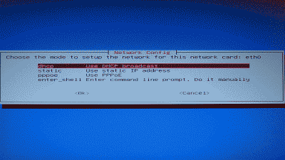
You’ll then be offered several choices on how Clonezilla should obtain IP network settings, including DHCP, static IP, PPPoE, or a shell prompt to manually define how it should go about doing obtain its settings. Select which option works best for you then select “Ok” (See Figure 5).

Screenshot of Clonezilla IP network configuration options

Figure 5

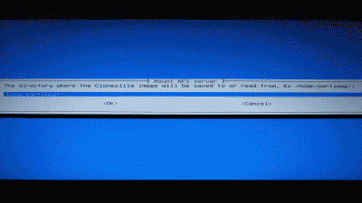
Clonezilla will then ask you whether it should use NFS version 2,3 or 4. Select “nfs NFS V2, V3,” then enter the IP address or the host name of your FreeNAS machine in the screen that follows. Next, you’re asked where the Clonezilla image will be saved to/read from. For the purpose of our example, we’ll enter “/mnt/files/images” to match the new directory we created earlier (See Figure 6).

Screenshot of Clonezilla option specifying where the image should be stored

Figure 6

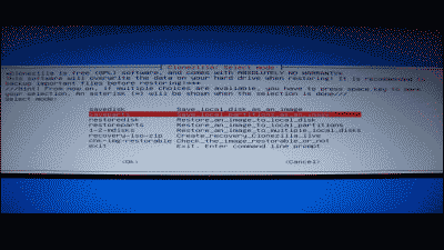
Clonezilla will then mount /mnt/files/images and display its current disk usage. Select “Enter” to continue and you’ll be given a choice to use Clonezilla in either a beginner or expert mode. Select “Beginner mode: Accept the default options” and you’ll be presented with a choice of whether to create images of the entire disk and/or one or more partitions (Note: this screen is also where you would choose to restore disk or partition images). If you would prefer to create an image of a partition, select “saveparts Save_local_partitions_as_an_image” where you will be presented with a choice of which partition(s) to create images of. For the purpose our example, however, we’ll select “savedisk Save_local_disk_as_an_image” to create an image of the entire disk (See Figure 7).

Screenshot of Clonezilla options allowing user to specify whether to create or restore the images of disks or disk partitions

Figure 7

Next, we’ll enter a name for new image and then chose whether we want to check and repair the file system before Clonezilla creates the image. This option is only for supported for certain Linux files systems, like ext3/4, and not for NTFS, so unless you have one of the supported file systems and have reason to suspect the file system may be in error, you should simply select “Skip checking/repairing source file system.” Clonezilla will then ask if you’d like for it to check if the image it creates will be restorable. Don’t worry, it performs this test without actually writing any data to the drive, so let’s select “Yes, check the saved image.” Now select “Enter” to continue, and confirm that you’d like Clonezilla to create the image by entering “y” at the prompt. Clonezilla will then create the disk image and write it to /mnt/files/images on your FreeNAS machine. When complete, Clonezilla will test to make sure the image is indeed restorable and then give the option of powering off the machine, rebooting, using the command line or start over. Congratulations! You’ve just created an image of your disk and stored it on your FreeNAS machine, where it will live safely and happily until you need it.

iceflatline