bookmark_borderInstall and Configure pfSense in Your Home Network

(20180226 – This post has been amended to reflect changes in pfSense version 2.4.2 — iceflatline)

This post will describe how to install and perform initial configuration of pfSense for use in a home network. pfSense (i.e., “making sense of packet filtering”) is a customized version of FreeBSD tailored specifically for use as a perimeter firewall and router, and managed almost entirely from a web-based GUI (“webConfigurator”). In addition to being a firewall and router, pfSense includes a long list of other features, as well as a package system allowing its capabilities to be expanded even further. pfSense is free and open source and its source code is released under the BSD license.

So, let’s get started…

Hardware Considerations

    Minimum requirements

The minimum hardware requirements for pfSense include a 500 MHz CPU, 512 MB of system RAM, 1 GB hard drive, and a minimum of two Network Interface Controllers (NIC). You’ll also need a CD-ROM drive or bootable USB drive in order to install pfSense to the hard drive. These requirements are extremely modest, but unless your data throughput requirements are fairly small, you’re likely going to want to use hardware offering a little better performance. Since a major contributor to throughput performance is the system’s CPU, let’s start there. pfSense published guidelines for CPU sizing recommends the following:

  • 10-20 Mbps – a modern (less than 4 year old) Intel or AMD CPU clocked at at least 500MHz
  • 21-50 Mbps – a modern 1.0 GHz Intel or AMD CPU
  • 51-200 Mbps – No less than a modern Intel or AMD CPU clocked at 2.0 GHz. Server class hardware with PCI-e network adapters, or newer desktop hardware with PCI-e network adapters
  • 201-500 Mbps – server class hardware with PCI-X or PCI-e network adapters, or newer desktop hardware with PCI-e network adapters. No less than 2.0 GHz CPU
  • 501+ Mbps – Multiple cores at > 2.0GHz are required. Server class hardware with PCI-e network adapters

Your choice of NICs will also have a significant impact on reliability and throughput performance. Low cost NICs, notwithstanding the potential long term reliability concerns, tend to rely much more on the system CPU to process segments and packets compared to their higher priced counterparts. Consequently, the better the NIC, the better the throughput performance you can expect from a given CPU. In short, don’t be too frugal when it comes to the NICs you use. Intel NICs are well supported under FreeBSD and always a good choice. If possible use discreet NICs rather than the on-board ones featured on many motherboards.

You should also ensure you have enough system memory. The pfSense hardware requirements recommend 1 GB of RAM. Whether or not you’ll need more will depend largely on how you decide to operate pfSense. Some of the add-on packages for example will increase RAM requirements significantly. Another factor to keep in mind when considering memory requirements is the number of active network connections. pfSense keeps track of active connections using a state table. The default state table size is 10,000 entries, each requiring ~1 KB of RAM or ~10 MB in total – likely more than adequate for handling most home networks. But, if you require a significantly larger state table, keep system memory requirements in mind.

    Compatibility

pfSense is purportedly compatible with any hardware supported by the FreeBSD version a particular pfSense build is based upon. pfSense version 2.4.2 for example is based upon FreeBSD 11.1-RELEASE. It’s always a good idea, however, to check the hardware you’re planning to use against the information contained in the FreeBSD 11.1-RELEASE hardware notes and the hardware compatibility section of the Frequently Asked Questions for FreeBSD 10.x and 11.x. The pfSense forums are another good resource, useful for gleaning the hardware compatibility experiences of others.

Installation

Performing a full installation of pfSense is a straight forward; however, before you get started there are a couple of preliminary steps I recommend. First, make a note of the Media Access Control (“MAC”) address for each NIC you’re installing in the system as well as its physical location in the motherboard. If your memory is as bad as mine, this will save you from wondering later “…now which NIC did I assign as the LAN interface?…” Second, disconnect the NICs from any LAN and WAN devices until you have the box up and running and configured to your requirements. Finally, if you have other hard drives in the system I recommend disconnecting them until the installation is complete so as to not accidentally install to the wrong drive.

Download a copy of the pfSense installer and burn it to a CD or place it on a bootable USB drive. After booting the system using the CD or USB drive and accepting the copyright and distribution notice, you’ll arrive at the initial installation screen (See Figure 1).

Screenshot of the initial installation screen in pfSense

Figure 1

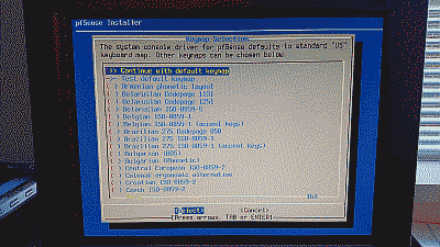
Select “OK” to continue. The pfSense installer will ask whether it should continue with the default U.S. keyboard key map or use a different one (See Figure 2).

Screenshot of the key map options available for the pfSense installation

Figure 2

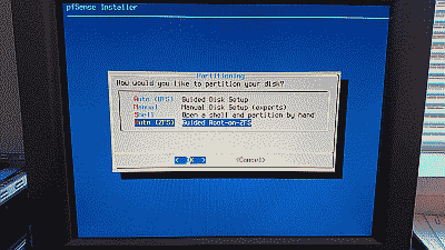
After configuring the keymap, the installer will ask and whether it should partition the hard drive using the UFS or ZFS file system. I advise using ZFS if possible (See Figure 3).

Screenshot showing the disk partition options available for the pfSense installation

Figure 3

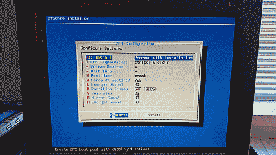
Unless your requirements call for something different, the default ZFS configuration options will work just fine (See Figure 4).

Screenshot showing the default ZFS configuration options available for the pfSense installation

Figure 4

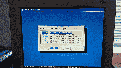
Next, the installer will ask you select a ZFS virtual device type. The steps in this post assume you’ll be installing pfSense on a single hard drive. The stripe option is the correct choice in this case. If your requirements call for installing pfSense using two or more hard drives then you have the option of selecting a mirror or one of the raidz virtual devices types (See Figure 5).

Screenshot showing the selection of ZFS virtual device type in the pfSense installation

Figure 5

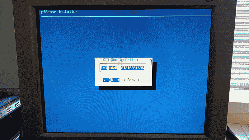
The installer will then ask you to confirm the choice of hard drives (See Figure 6).

Screenshot showing the confirmation of the hard drive used for the pfSense installation

Figure 6

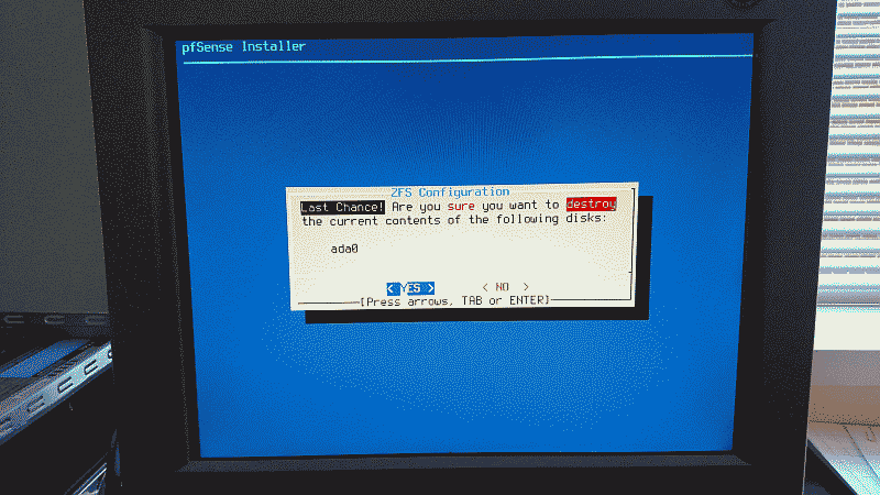
Finally, the installer will offer one last chance before destroying any previous content contained on the hard drive and continuing with the installation. If you’re satisfied with your configuration choices select “YES” to proceed (See Figure 7).

Screenshot showing final confirmation before installing pfSense to the hard drive

Figure 7

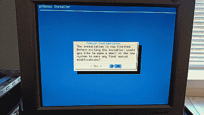
After the installer finishes the installation you’ll be offer the opportunity to open a shell session in order to make any modifications manually (See Figure 9).

Screenshot showing the prompt to open a shell session to make installation configuration changes manually

Figure 8

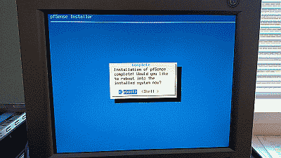
If no further changes are required select “No” the installation will be complete and the system will ask to be rebooted (See Figure 9).

Screenshot showing the prompt to reboot the system after pfSense completes installation

Figure 9

Configuration

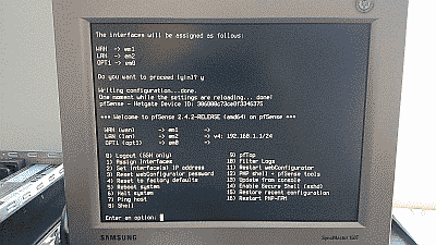
After pfSense is installed and the system rebooted, you’ll arrive at the pfSense console menu (See Figure 10).

Screenshot showing the pfSense console menu

Figure 10

Note that in this example pfSense has chosen the NIC assigned the device name em1 as the WAN interface, and em2 as the LAN interface (I have a third NIC in this system, which is why you see an em0 device). If you’d like to reassign these interfaces or simply want to know which MAC address belongs to each NIC, then select “Assign Interfaces” (menu option 1). Note also that pfSense initially assigns the LAN interface the default static IPv4 address of 192.168.1.1, and configures the WAN interface to use DHCP so you will not see an IP address assigned to that interface.

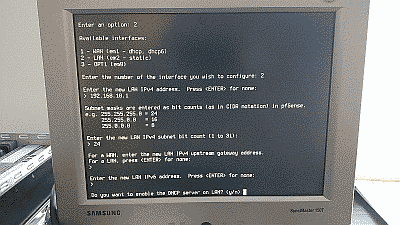
Select “Set interface(s) IP address” (menu option 2) to configure pfSense’s LAN interface IPv4 address to one that will fall within the subnet you plan to use for your network. In this example we’ve configured the IPv4 address to 192.168.10.1, assuming that the subnet will be 192.168.10.0/24.

Screenshot showing the configuration of the IPv4 address for the LAN interface in the pfSense console menu

Figure 11

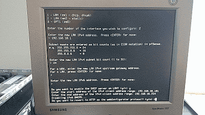
This menu option also allows you to activate pfSense’s DHCP server and define a range of IPv4 addresses for the server to use. In this example we’ve configured the DHCP address range to be 192.168.10.101 to 192.168.10.254 (See Figure 12)

Screenshot showing the configuration of the IPv4 DHCP address range in the pfSense console menu

Figure 12

Once the IPv4 address and DHCP server are configured, you’ll be asked if I want to revert to HTTP as the webConfigurator protocol (as opposed to using to using HTTPS). I recommend declining this option to improve login security. After these steps are completed you will be returned to the console menu.

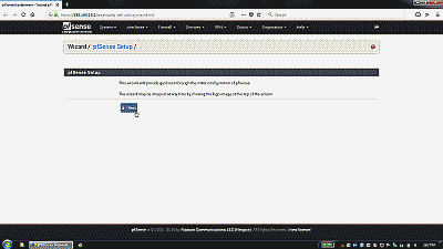
Now, connect to the LAN interface, fire up your web browser, and navigate to IPv4 address you assign to the LAN interface to access the pfSense webConfigurator. The webConfigurator login is password protected – the default login is admin and the password is pfsense. The first time you login to a new installation of pfSense, you ne greeted with the pfSense setup wizard to perform an initial configuration (See Figure 13).

Screenshot showing the pfSense setup wizard

Figure 13

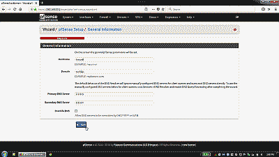
The setup wizard starts by asking you to define the hostname for your new pfSense system, the domain where it will reside, and primary and secondary DNS servers. You can use any hostname you’d like but be aware of the following constraints: the hostname you choose must start with a letter, and after that contain only letters, numbers or a hyphen (e.g., “firewall” or “firewall-1”). The “Domain” field can be filled in with any fully qualified domain (e.g., “mysite.org”) or a name of your choice (e.g., “homenet”). The hostname and domain fields are combined to create the fully qualified domain name of your pfSense box (e.g., “firewall.mysite.org” or “firewall.homenet”). If your service provider provisions your service using DHCP, then the DNS fields will be likely be filled in automatically when you connect to your provider. If you plan to use a static WAN IP address, or simply prefer to use alternative DNS providers, then you should provide at least a primary DNS address at this point (See Figure 14).

Screenshot showing the general information section of the pfSense setup wizard

Figure 14

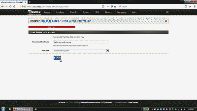
The next wizard screen is where a time server hostname and timezone are defined. I recommend using the default host 0.pfsense.pool.ntp.org, which results in a random server from a pool of known good NTP servers to be chosen automatically (See Figure 15).

Screenshot showing the general time server information section of the pfSense setup wizard

Figure 15

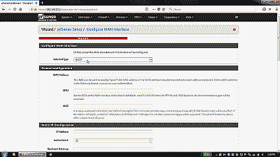
Next, you’ll be taken to the WAN section of the setup wizard. If your service provider provisions your service using DHCP, then you simply need to select “DHCP” from drop-down list, otherwise chose the appropriate service type. The “MAC Address” field under “General configuration” can be used to enter a MAC address that will pose as the MAC address of your WAN interface NIC. The “Block RFC1918 Private Networks” and “Block bogon networks” sections are selected by default in order to block invalid traffic from entering your network. The remaining sections in this portion of the setup wizard are specific to WAN service type chosen (See Figure 16)

Screenshot showing the configure WAN interface information section of the pfSense setup wizard

Figure 16

After the WAN section, you’ll encounter the final two sections of the setup wizard. These provide the opportunity to change, if desired, the LAN IP address as well as the default password for the admin user account. Note that this password also serves as the password for SSH access as well as the console menu (should you decide to password protect it).

At the conclusion of the setup wizard, you’ll select “Reload” and after a few moments be returned to the pfSense webConfigurator. At this point basic connection options are configured enough to allow the pfSense box to be safely connected to the service provider and LAN. However, before bringing pfSense online in your network there are a couple of optional changes to its configuration you may wish to consider.

    Disable webConfigurator login autocomplete

By default login credentials for the webConfigurator may be saved by a web browser. Navigate to System->Advanced->Admin Access and select “Disable webConfigurator login autocomplete” to disable autocomplete on the login form so that browsers will not prompt to save credentials (Note that some browsers do not respect this option). When complete, select “Save”.

    Password protect the console menu

While pfSense is managed almost entirely from its webConfigurator, it does allow some configuration management through its console menu (See Figure 10). By default, pfSense does not secure this menu, therefore, anyone who can physically connect a monitor to the pfSense machine will have root level shell access. To prevent this (or at least make it more difficult), navigate to System->Advanced->Admin Access and select “Password protect the console menu.” When complete, select “Save.” You’ll need to reboot the system for this change to take effect. Note that the user name for the console menu is always admin or root and the password will be “pfSense” by default, or the one you chose if you elected to change the default admin password when running the setup wizard. It’s also worth noting here that if you create a new user, this new user will only be allowed access to a command line prompt at the terminal, not the console menu itself, even if you add them to the system’s admins group (See System->User Manager).

    NAT Reflection mode for port forwards

By default pfSense prevents hosts within the LAN from accessing your public IP addresses. This can be inconvenient at times, particular when testing port forwarding from within the LAN. To change this, navigate to System->Advanced->Firewall & NAT and, depending on your requirements, select either “NAT + proxy” or “Pure NAT” from among the options in the drop down list under “NAT Reflection mode for port forwards”. When complete, select “Save”. A reboot is not needed when selecting this option so you can use it on an as-needed basis if desired.

    Packages

As mentioned, pfSense offers a fairly extensive package system allowing you to extend its capabilities. To find a list of packages that can be added, navigate to System->Package Manager->Available Packages to view the available software packages.

    Firewall

Setting up NAT port forwarding and firewall rules in pfSense can be a bit daunting at first. Once you get the hang of it though you’ll realize just how flexible and powerful the system is. Options for configuring port forwarding and firewall rules can be found under Firewall->NAT and Firewall->Rules respectively. I recommend setting up any port forwarding rules you may have first. Then, for each port forwarding rule, you’ll need to set up an associated firewall rule. When complete, select “Save”, then “Apply changes”.

    DHCP

Options for configuring the DHCP server on the LAN interface can be found under Services->DHCP server. If you’re deploying pfSense in a typical home network where the availability of IP addresses is not a concern, one option you may want to consider changing is the default lease time of 7200 seconds (two hours) in order to reduce the number of lease requests in the network. This is also the section where you can assign static IP addresses to hosts, if desired. For example, you may wish to assign static IP addresses to servers and network devices (managed switches, network printers, etc.), as well as to any hosts you intend to build long-term port forwarding rules for.

    UPnP

If you have game consoles like Microsoft Xbox, you know what a pain it can be at times to get them to connect reliability to services like Xbox Live through your home network gateway/firewall. A common solution is to forward the necessary ports to these devices, but what if you have more than one? If you want one or more game consoles to have reliable access to their respective services, the only real solution is to use Universal Plug and Play (UPnP). Fortunately, pfSense’s UPnP service works remarkable well. To activate it, navigate to Services->UPnP & NAT PMP and select “Enable UPnP & NAT PMP” and “Allow UPnP Port Mapping” then ensure that the LAN interface is selected under “Interfaces”. When complete, select “Save”. That’s it. Your game consoles will discover pfSense’s UPnP server and the necessary port forwarding rules will be built automatically as needed. You can check which ports have been forwarded by navigating to Status->UPnP & NAT PMP.

    Wake on LAN

The Wake on LAN in feature in pfSense allows you to instruct it to send the Wake on LAN “magic packet” to a network host you need to power up. To setup Wake on LAN, navigate to Services->Wake-on-LAN and select the “+ Add” icon. Select the LAN interface and enter the MAC addresses for the host you’d like to send magic packets to. When complete, select “Save”.

    System Logs

You may wish to have log entries arranged so that the newest entries appear first. To do that, navigate to Status->System Logs->Settings and select “Show log entries in reverse order (newest entries on top)”. When complete, select “Save”.

Remote Access

pfSense’s webConfigurator uses HTTPS and port 443 by default, and accessing it remotely is simply a matter of navigating to your WAN address. Unfortunately, many ISPs block incoming port 443 traffic. You can chose an alternate incoming TCP port by navigating to System->Advanced->Admin Access and entering the port number in the “TCP port” field. When complete, select “Save”. You will also need to create a new firewall rule under Firewall->Rules that will allow a connection on the WAN interface to pass through to pfSense’s webConfigurator server on the port you specify. At a minimum, this rule should define following parameters:

Action: Pass
Interface: WAN
TCP/IP Version: IPv4
Protocol: TCP
Destination: WAN address
Destination port range: your alternate webConfigurator port selection
Description: web admin

pfSense’s SSH server may also be enabled to allow remote access to the console menu via an SSH client. To enable the SSH server, navigate to System->Advanced and select “Enable Secure Shell”. For improved security, I recommend using an incoming port other than 22 and a key-based login instead of a password. To use a key-based login, select “Disable password login for Secure Shell (RSA/DSA key only)” and select “Save”. Then navigate to System->User Manager and paste your public key into the “Authorized SSH Keys” field. When complete, select “Save”. Note that your public SSH key is stored in /root/.ssh/authorized_keys. Should you need help generating a public/private key pair please see my post Remote Access To Your Ubuntu Server Using PuTTY, Hamachi and SSH. Don’t forget to create a new firewall rule under Firewall->Rules that will allow a connection on the WAN interface to pass through to pfSense’s SSH server should you decide to use an alternate SSH port.

Conclusion

This concludes the post on how to install and configure pfSense on your home network. pfSense isn’t hard to configure nor complicated to manage, and proves to be a nice open source package for implementing a robust and scalable perimeter firewall and router.
bookmark_borderFixing Ethernet Connection Problems on the Lenovo ThinkPad T410

Earlier this year I purchased a Lenovo ThinkPad T410 laptop. Nice box. But shortly after purchasing it I began to notice that its ethernet adaptor would lose connection on a regular-yet-random basis regardless of the network I happened to be on. I dual-boot with this machine and I did not seem to be experiencing the same problem while running Ubuntu. So… I suspected the culprit might be my Windows 7 network driver. Sure enough, after trying several versions of Lenovo-supported drivers, the ultimate solution to this problem was to dump the Lenovo driver completely and download the driver for the 82577LM ethernet controller directly from Intel. Problem solved.

Note that in addition to the installing the base driver for the ethernet controller, the package will also give you the option to install Intel PROSet for Windows Device Manager, Intel Advanced Networking Services, and SNMP for Intel network adapters for Windows 7. The first two are selected for you by default. If installed, Intel’s PROSet software provides a custom device manager property page for the adaptor which has some pretty nice features, including diagnostics. Contrary to its name, the Intel Advanced Networking Services feature does not install additional Windows services, rather it installs a couple of extra tabs in the aforementioned device manager property page allowing you to setup and manage teaming and V-LAN tagging on the adaptor. The SNMP for Intel network adapters feature is simply an SNMP agent enabling you to send event notifications via SNMP (requires that the Windows SNMP service be running).

bookmark_borderIntel Core i7 Build: Overclocking the Intel DP55KG and Core i7 860

This is the third post documenting my upgrade to an Intel Core i7 Lynnfield system. In my first post I discussed the components I selected and why. I talked about assembling the system and some of the challenges I encountered in my second post, and in this final post I’ll be discussing my efforts at overclocking the Intel DP55KG motherboard and Core i7 860 processor.

Two Approaches

Intel’s new “Turbo Mode” feature is able to increase the processor multiplier value beyond its default value (21 in the case of the Core i7 860) if the processor is operating within what it considers are safe temperature parameters. For example, in Intel’s Core i7 Bloomfield architecture, processors are allowed to raise the stock multiplier value by 1 or 2 depending on the number of cores being used. Intel’s Lynnfield processors are considerably more aggressive with Turbo Mode, increasing Turbo Mode multipliers within a range of ~2-5. Essentially what this means is that when fewer processor cores are demanded by an application or process, larger multiplier values are used, thus the processor is allowed to run faster than the default multiplier would normally allow. In the case of the Core i7 860, it’s not uncommon, for example, to see it use a multiplier value of 26 in single-threaded applications, yielding a processor speed of 3.46 GHz, well above its stock speed of 2.8 GHz. While this sort of dynamic overclocking is pretty damn impressive, a question arose for me when it came time to overclock my Intel DP55KG and Core i7 860: should I attempt to overclock the system with Turbo Mode enabled, meaning I would have to consider the headroom required when higher multiplier values are used, or should I simply disable it and go with the more traditional overclocking approach? I ended up trying both approaches to see how they compared and to evaluate which would work best for me.

Regardless of which approach you use though, overclocking a Lynnfield system is pretty straight forward. Adjust the host clock frequency until the system achieves a stable CPU speed. From there, the memory multiplier can be adjusted to compensate for the change in host frequency. If desired/needed you can also adjust the CPU voltage, memory voltage, and Uncore voltage to further stabilize the system. That’s pretty much all the adjusting the architecture allows you to do.

    Turbo Mode enabled

My first attempt at overlocking the Intel DP55KG and the Core i7 860 involved raising the host clock frequency but leaving with Turbo Mode enabled. These are the BIOS settings I started with:

Performance

Host Clock Frequency Override: Manual

Performance -> Processor Overrides

CPU Voltage Override Type: Dynamic
CPU Voltage Override: Default (default)
CPU Idle State: High Performance
Intel Turbo Boost Technology: Enabled (default)

Performance -> Memory Configuration

Performance Memory Profiles: Manual – User Defined
Memory Multiplier: 12
Memory Voltage: 1.65
Uncore Voltage Override: 1.10 (default)

Performance -> Bus Overrides

All settings in this section were left at their default values.

Power

Enhanced Intel SpeedStep Tech: Enabled (default)
CPU C State: Enabled (default)

With this approach, my objective was to try to achieve the best stable overclock I could using Turbo Boost and leaving the voltage settings at thier default values. However, I did alter two voltage settings: the CPU Voltage Override Type, which I set to Dynamic, allowing the CPU to still manage its own power usuage but with higher upper limits; and the Memory Voltage, which I set to 1.65 to match the voltage input specified for my Mushkin DDR3-1600 kits. I left the RAM timings at the default SPD values of 9 9 9 24.

And the result? I was able to achieve a host clock frequency of 154 MHz before the system became unstable (stability in this case is defined as the ability for the system to run without failure using Prime95 (v25.9) Large FFT for 2-3 hours). This yielded a CPU speed of 4 GHz, assuming a Turbo Boost multiplier of 26 (154 * 26 = 4.00 GHz). I did notice, however, that the multiplier in my case generally liked to stay at 25 a large percentage of the time during idle. I suspect this was the result of the High Performance setting in BIOS that forces the system to use the higher multiplier when the operating system would otherwise be allowed to lower it.

According to CPU-Z (v1.53) The CPU voltage (VID) fluxuates between .8 and .9 at idle and core temperatures according to Speedfan (v4.40) were ~30c at idle. Given the DRAM multiplier setting of 12, the DRAM frequency weighed in at a nice 1848 MHz. Loading all four cores resulted in VID rising to 1.096 volts and core temperatures to ~63c. Using all four cores of course also resulted in the system using the default CPU multiplier value of 21 (154 * 21 = 3.23 GHz).

So, in summary, I was able to achieve ~15% overclock under load using Turbo Boost and leaving the voltage settings at thier default values.

    Turbo mode disabled

After determining the optimal overlocking settings for my Intel DP55KG and the Core i7 860 using default voltages and Turbo Mode enabled, I attempted to overclock the system with Turbo Burst disabled as well as the freedom to use higher voltage settings, if necessary, to make the system stable. These are the BIOS settings I started with:

Performance

Failsafe Watchdog: Enable (default)
Host Clock Frequency Override: Manual
Host Clock Frequency: 133

Performance -> Processor Overrides

CPU Voltage Override Type: Static
CPU Voltage Override: Default (default)
CPU Idle State: High Performance
Intel Turbo Boost Technology: Disabled

Performance -> Memory Configuration

Performance Memory Profiles: Manual – User Defined
Memory Multiplier: 10
Memory Voltage: 1.65
Uncore Voltage Override: 1.10 (default)

Performance -> Bus Overrides

All settings in this section were left at their default values.

Power

Enhanced Intel SpeedStep Tech: Disabled
CPU C State: Disabled

And the result? With Turbo Burst disabled and the latitude to increase VID and other voltage settings if necessary, I was able to achieve a host clock frequency of 170 MHz using a VID of 1.2 before the system became unstable, yielding a CPU speed of 3.5 GHz (170 * 21 = 3.57 GHz). Further increases in VID, memory or Uncore voltage did not allow for a stable system using higher clock speeds. Core temperatures rose to ~35c at idle and loading all four cores caused the core temperatures to rise to ~74c. With a the DRAM multiplier setting of 10 instead of 12, the DRAM frequency fell to 1700 MHz. Here again I left the RAM timings at the default SPD values of 9 9 9 24. I did try to run with the DRAM multiplier set at 12 but there was just no way my 1600 MHz RAM was going to run at 2040 MHz!

So, in summary, I was able to achieve ~28% overclock by shutting down Turbo Boost and raising VID to 1.2.

Comparison

Afterwards, I threw a few highly unscientific tests at both cases to see how they compared. The first involved transcoding a typical MPEG-2 DVD *iso to the h.264 high-profile format using Handbrake. There was no significant difference in time between the two methods, however both represented a nice improvement over the default settings. Turbo Boost, however, did provide a nice bump in memory bandwidth, due mostly to the ability to run at a higher DRAM multiplier value. The use of Turbo Boost also won out when running 3DMark Vantage, suggesting that the higher multipler values played a role. The game-based tests I ran were essentially useless since the particular games I had on hand to test with (BattleForge, Crysis, and X3 Terran Conflict) more strongly rely on the GPU for performance improvement and not the CPU.

Conclusion

Turbo Mode is something that should be evaluated based on your needs and the specifics of your overclock. Which one did I go with? I decided to run with Turbo Mode enabled and the lower host clock frequency. There were a couple of reasons for this choice. First, I rather like using the default voltage settings; by allowing Intel to manage the power settings, I’m able to run my system moderately faster, and in some cases a hell of a lot faster, but also a lot cooler. Second, I typically run applications that do not utilize all four cores, so a moderate overclock with Turbo Mode gives me better results than a higher-speed overclock without Turbo Mode. However, it’s good to know that as I grow to depend on more cores consistently, I can simply shutdown Turbo Boost and clock the system higher.

bookmark_borderMy Intel Core i7 Build: Putting It Together

Recently I decided it was finally time to upgrade my gaming computer. I had skipped over Intel’s recent spate of chipsets, as well as Windows Vista, so my computer – still based on the Intel x975 chipset and Windows XP Pro – was definitely in need of an upgrade.

This is the second post documenting my upgrade to an Intel Core i7 Lynnfield system. In my first post I discussed the components I selected and why. In this post I’ll talk about assembling the system and the challenges I encountered. In my final post I’ll cover my attempts at overclocking the new system.

The Build

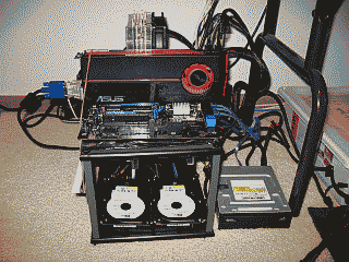
I like to build systems outside of the case. Then, when I’m sure everything is running well, I’ll place the components in the case and dress up the wiring (See Figure 1). Similar to other motherboard manufacturers, Intel has finally taken to mounting the SATA II ports horizontally, facing the back of the case, instead of vertically. Good thing too because the video card would likely have prevented me from using the first couple of ports. I’m using two 36GB Western Digital “Raptor” drives configured for Raid 0 to hold the OS. I placed these on SATA ports 0 & 1. I also have a pair of 74 GB Raptors will be configured for Raid 0, but these will become my d:\ drive and hold only data files. I placed these drives on SATA ports 2 & 3. My CD/DVD drive then ends up on port 5.

 Screenshot of my Core i7 build outside of the computer case

Figure 1

I decided to get a new power supply for this rig. The existing PC Power & Cooling Silencer 750 that I originally intended to use for this upgrade I felt could best be used elsewhere. I’m partial to the single 12 VDC rail design for PC power supplies so I ended up picking up Corsair’s’s 750TX.

Intel offers several methods for updating their BIOS, including updating directly from the OS using a utility called “Express BIOS Update.” Sans OS though, your choice is to use Intel’s tried and true “IFLASH2” utility and the BIOS file from a bootable floppy, USB or optical disk, or use a bootable ISO image to update the BIOS firmware. I chose the latter and it was a breeze. Burn the image to a CD-R, boot to it, and in 5 minutes your BIOS firmware is updated.

In order to build the RAID arrays, I navigated to Advanced -> Drive Configuration -> Configure SATA and made sure that the RAID option was selected, then rebooted and entered Intel’s Raid configuration utility (using CTRL-l). I chose the default stripe size of 128 KB for my two RAID 0 arrays. Returning to the BIOS, I made some additional preliminary tweaks before installing the OS, including disabling the 1394 port (never use it), disabling CPU and System fan control (I prefer to run them wide open), and turning off the Event Log (this is a feature?). Adjustments to Performance section of the BIOS will be saved for when I start overclocking the system. I then booted into Memtest86+ (v4.00) and ran it for 2-3 passes to verify that the RAM was solid. Sweet, no errors.

Windows 7 comes with native support for RAID, so rather than choosing to install my own via the usual “F6” method I let Windows use its own. After the OS was fully operational though, I installed Intel’s RAID driver, as well as the essential audio, LAN and graphics drivers; activated the OS and downloaded Microsoft updates. I then installed applications and performed the my usual OS performance tweaks. With the exception of a few applications, such as Guild Wars and Quake 3 Arena, which I made run using compatibility mode, all my applications installed and ran just fine on Windows 7 Pro 64-bit.

My Canon i560 printer had me scratching my head though. First, Canon’s Windows 7 64-bit driver for the i560 does not work; and, to complicate things, my printer is parked on a D-link print server. To install a driver that would allow this PC to see the printer, I first had to connect the printer directly to the PC via USB. Then, instead of messing further with the flaky Canon driver, I let Win 7 find and use its own native driver. Then I deleted that printer and put the printer back on the print server. I created a new printer, but this time configured for a proper TCP/IP port. When it came time to load a driver, I simply reused the one Win 7 added when the printer was directly connected.

The Temp

Almost immediately after I get a new system up and running on the bench I navigate to the BIOS’s hardware monitor to verify the temperature(s) it’s reporting for the CPU so as to ensure I have the heatsink and fan installed and working correctly.

Back in the good old days (you know, before Core i7), you would typically pay attention to the “CPU temperature” the motherboard was reporting. This is the processor’s Tcase temperature, the temperature at the geometric center of the topside of the integrated heat spreader as measured (or estimated) by a sensor IC. This temperature value is routinely used by utilities such as Everest, SpeedFan, as well as ones provided by the motherboard manufacture, to report the thermal condition of the processor. According to Intel, Tcase should be maintained at or below the thermal threshold listed in the processor’s datasheet. For the Core i7 860 processor for example, that value is 72.7C. Given a reasonably accurate measurement of Tcase and the not-to-exceed threshold value provided by Intel, you knew exactly where you stood with respect to your processor’s temperature.

Enter core temperatures. Unlike Tcase, the processor’s core temperature is the temperature measured by the processor’s Digital Thermal Sensor (DTS). This value is always relative to what Intel feels is the maximum core temperature threshold for a given processor model, a parameter Intel calls TjMax. Nominal core temperature values, as reported by utilities such as Core Temp and Real Temp, would be an equally reliable way of representing processor temperature if you knew with certainty the value of TjMax. Knowing that value would provide you with a fairly reliable way to calculate your core temperature, and by extension, how much margin you have before encountering TjMax:

Core Temperature = TjMax – DTS reading

Unfortunately, Intel treats the TjMax value as if it were a matter of national security, and so these utilities are left to essentially guess what the TjMax value is in order to report the nominal core temperature values. In other words, core temperatures, while nice to know, aren’t terribly useful because: 1) Their accuracy is suspect; and 2) there is no direct correlation to the nominal value of Tcase and it’s threshold as provided by Intel in the processor’s specification.

On the Intel DP55KG that I’m using for this upgrade, the situation seems to have gotten even murkier. On this motherboard there are two temperature readings reported in BIOS: Internal and Remote. Instead of Tcase, this Internal temperature is apparently meant to represent the processor’s core temperatures. This was confirmed when, after installing Real Temp, the temperatures reported by that utility matched the one reported by the BIOS within about one degree. Speedfan’s readings also closely matched these readings. And the “Remote” temperature reported by the BIOS? Since it routinely reports temperatures 2-5 degrees below those reported by the Internal reading, I suspect its readings come from a thermal sensor near the processor, whose job it is presumably to keep track of the internal case temperature.

It appears then that Intel now seems to be more interested in focusing on core temperatures and their relative difference from TjMax. But how does this help me ascertain how much headroom I have with respect to the Core i7 860’s thermal profile value of 72.7C? In short, it doesn’t. So I guess I’ll need to trust that Intel will keep the processor from exceeding whatever it feels are its critical thermal thresholds, Tcase or otherwise. My job, it appears, is merely to keep the core temperatures as low as possible.

The DP55KG’s BIOS was reporting that the processor’s core temperature was idling at ~36C (ambient room temperature is routinely ~20C). I felt I could probably do better than this so I went in search of a heatsink to replace the Arctic Cooling Freezer 7 Rev.2 I was using for this build. As mentioned in my initial post, even finding a suitable heatsink for an LGA1156 CPU was a challenge. While there were plenty of options for 1366-based boards at the time I was pulling the parts together for this build, very few of the more reputable heatsink manufactures had yet to put out parts made specifically for with newer LGA1156. The second time out though I ran into a Maximum PC article regarding the Cooler Master Hyper 212 Plus air cooler.

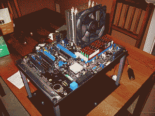
I picked one up, replaced the Freezer 7, and was able to lower the idle temperature to 30C. Needless to say I’m quite happy with it. As you can see though, the heatsink does land very close to the RAM modules (See Figure 2).

 Screenshot of proximity of the heatsink to the RAM

Figure 2

This brings up another issue that would be a good to mention here and that’s the best procedure I found for applying the thermal compound. Arctic Silver suggests applying their Arctic Silver 5 product in a line over the CPU heatspreader horizontally, but not spread the line out. Instead, when you place the heatsink on top of heatspreader of the CPU, the line of Arctic Silver 5, they suggest, will “spread out just like an oval pancake.” Well, it did spread out a bit and it may resemble an oval pancake (See Figure 3), but this method does not yield the best results. I tried several variations of this pancake method and compared the results with the more traditional method of placing a small amount of compound in the center of the processor and spreading it thinly and evenly so it covers the entire top of the processor, and in each case the latter method produced the best results.

 Screenshot of the Core i7 860 and the result of applying a thin horizontal line of thermal compound

Figure 3

I think the problem with Arctic Silver’s method is that it actually places too much compound on the processor resulting in poorer heat transfer, not better. But perhaps a more significant factor leading to poorer results in my case is the unique design of the Cooler Master 212’s heatsink itself. Instead of the typical smooth copper surface, this heatsink is built in such a way as to allow its heat pipes to rest directly on the processor. Consequently, the heatsink surface is not smooth but instead has ridges where the heat pipes nestle against a nickel plate. These ridges seem to be preventing the thermal compound from spreading out as well as Arctic Silver intended (See Figure 4).

 Screenshot of the Core i7 860 and the result of applying a thin horizontal line of thermal compound

Figure 4

Final Thoughts

After putting each of these speed bumps behind me I was ready to place all of the components in the NZXT Tempest mid tower case. I decided to forego using the case’s side fan in order to improve positive air flow, but even with one less fan, it was immediately apparent that I was going to run out of fan headers. No worries though, I typically run the fans wide open anyway so I simply wired 12VDC to each of them. The Tempest isn’t the easiest case to dress up wiring in but I managed hide some of it behind the motherboard (See Figure 5).

 Screenshot of the Core i7 860 and the result of applying a thin horizontal line of thermal compound

Figure 5

In the next post I’ll share my experiences with overclocking the DP55KG and Core i7 860.

bookmark_borderMy Intel Core i7 Build: The Parts

I’m fortunate (or cursed) enough to be able to upgrade the desktop computers here at the iceflatline compound fairly often. The way this usually works is that my personal desktop computer gets overhauled and then the older parts are used to build, upgrade and/or maintain the other machines in the house – call it the “trickle down” method of upgrading.

Recently I decided it was time to start this cycle again. I had elected to skip over Intel’s X38 and X48 chipsets (and p45/p55 chipsets too) and Windows Vista, and so my computer – still based on the x975 chipset and Windows XP Pro was definitely in need of an upgrade.

This will be the first in what I intend to be three related posts documenting this upgrade – the parts I selected for it and why; the assembly of the system and the challenges I encountered; and finally, the steps taken to overclock the system.

The Parts

I’ve built a good many PCs over the years. Everything from bleeding-edge, fire breathing, water-cooled dragons to systems just fast enough to run Puppy Linux. My goal this time was to use the best quality components I could find for a low price, and build a fast, reliable machine for right around $1000 – $1500. In other words, build a machine that’s a good value. Since this was an upgrade, I also had a couple of other objectives in mind. First, since this machine, like its predecessor, would be used primarily for PC gaming and the occasional video/audio project, I wanted to upgrade the graphics capability; second, I wanted to significantly increase the amount of system memory; and finally, I wanted to use Windows 7.

The case – I’ve been a fan of Lian Li cases for some time; however, while they look great and their quality is second-to-none in my opinion, they’re not what you would characterize as a “gamer” or “enthusiast” case. This is primarily because they typically lack good cooling. I’m currently using water cooling in one of their tower cases and so the lack of good case cooling has not really posed a problem for me. However, I wanted to try and save on what I anticipated would be the cost for a new water cooling solution to fit a new motherboard and instead go with air cooling if I could. That steered me towards a mid-tower case with good air flow. I decided on the NZXT Tempest case. I had built a system for one of my kids with this case and really liked it. The three 12cm fans provide good air flow; it’s easy to work in, and it looks good.

The power supply – This was an easy one. I almost exclusively use power supplies from two manufacturers. For lower cost builds I use Fortron and for everything else I use PC Power & Cooling. I was already using a Silencer 750 in my current system so my solution here is to simply reuse this unit.

The CPU – This was a tough choice. Being somewhat of an Intel fan boy I had more or less settled on going with one of their Core i7 products. But Intel has presented a very challenging decision for the gamer/enthusiast building a new system today. Intel’s newest CPUs – code-named Lynnfield – include the 2.93GHz Core i7-870, the 2.83GHz Core i7-860, and the 2.66GHz Core i5-750. Lynnfield chips use essentially the same “Nehalem” 45 nm architecture as Intel’s other Core i7 CPUs, code-named “Bloomfield.” However, the Lynnfield CPUs are incompatible with existing Bloomfield-based Core i7 motherboards. The most notable difference is Intel’s decision to use a new socket for the Lynnfield CPUs – LGA1156, which is incompatible with the current Bloomfield-based CPUs. To make matters even worse, the fan/heatsink mounting holes for each socket type are also incompatible.

A significant advantage in using Bloomfield is Intel’s use of tri-channel DDR3 memory (to save cost, Intel uses dual-channel DDR3 for Lynnfield). So then why go with Lynnfield if a bigger memory bus is arguably better? I want a fast rig right, and I have to get a new motherboard in either case. Well, for one thing, LGA1366 motherboards aren’t cheap. Those added traces from the socket to the RAM slots to support tri-channel RAM mean more layers and pricier motherboards. Yet another factor to consider is that while Lynnfield is cheaper and gets you 90 percent the performance of a Bloomfield system, Intel will purportedly introduce a yet another new CPU skew in 2010 (“Gulftown”). This architecture supposedly adds two more physical cores to the CPU, add to that hyper-threading, and that’s 12 threads available to the OS. But alas, it will only be available on the Bloomfield/LGA1366 platform.

But, after weighing all these factors and the desire to stay true to be goal of pulling together the best system for the money, going with a Lynnfield build made the most sense to me. I chose the 2.83GHz Core i7-860, which should overclock quite well and, for ~$280.00, would seem to be the sweet spot for price versus performance. I also save at least $100 on the board and a little more on the RAM. However, I arguably give up a clearer upgrade path by passing on a Bloomfield-based system.

The Motherboard – I’ve traditionally used ASUS motherboards but then started to run into reliability problems with them. I also grew tired of the growing list of “features” their boards began to offer that I had no use for (e.g. WiFi, Bluetooth, etc.), resulting in time spent trying to disable them somehow. For my last build I used Intel’s D975XBX2, the so called “Bad Ax” board, and really liked it. No it didn’t have all the candy-ass features and overclocking capabilities of say an ASUS or Gigabyte motherboard at the time, but it turned out to be sufficiently overclockable for my needs and has been 100% reliable. Given this experience, I decided to go with an Intel motherboard again and chose their DP55KG.

The Heatsink – The Corsair Nautilus 500 water cooling solution I’m currently using, while it has served me well, wouldn’t be useable on the new LGA1156 motherboard. Besides, Intel’s latest CPUs run cooler than their predecessors and air cooling has gotten significantly more effective. So, there just wasn’t any reason in my mind to hassle with another water cooling solution for this build. However, finding a suitable fan/heatsink for an LGA1156 CPU turned out to be somewhat of a challenge. As I mentioned, the fan mounting holes for LGA1366 and LGA1156 motherboards are incompatible. So while there were plenty of options for 1366-based boards at the time I was pulling my parts together, very few of the more reputable heatsink manufactures had yet to put out parts yet that were made specifically for with newer.LGA1156. I ended up choosing the relatively inexpensive Arctic Cooling Freezer 7 Rev.2 with the hope of finding something a perhaps a bit more effective in a couple of months when other companies started to release parts for the LGA1156 motherboards. I also chose Arctic Silver 5 for the thermal compound.

The RAM – One of my goals for this build was to double my system memory. That meant 8GB for this build. After all, this is supposed to be an upgrade right? I was looking for either an 8GB kit (2x4GB) or two 4GB (2x2GB) kits with the timings as low as possible. Another factor that I was glad I considered ahead of time was whether the RAM would fit under the CPU’s fan/heatsink due to the close proximity of the RAM slots to CPU. I ended up eliminated a couple of products (Corsair Dominator I’m looking at you…) because they were too tall to fit. I ended up selecting two 4GB DDR3-1600 Mushkin Redline kits from which run at 1.65v with timings that spec at 7-7-7-18.

The Graphics – I have no allegiance to either AMD or Nvidia and was willing to go with either depending on price versus performance. I ended up going with AMD this time around though and chose a Radeon 5870 from ASUS. For ~$380, I felt it provided the best performance for the money.

The Optical Drive – Believe it or not I actually had to buy one of these. The Lite On drive I’m currently using is IDE and I needed one with a SATA interface. Sadly, I guess it really is time to move on. Here’s how much time I spent shopping for it though – I went to Newegg.com, navigated to the CD/DVD burners, selected “Best Rating” from among the search options and dutifully paid for the one that was at the top of the list. I think it was from Samsung :).

The Hard Drive – This was a tough decision too. I really really wanted to get a solid state drive but with prices so high and firmware support for features like Trim so fluid I decided to stick with with my trusty Western Digital Raptors that I currently have set-up in Raid 0. I fully expect that SSD performance will improve and prices will come down soon so I plan on revisiting this at a later time.

The OS – Not much of a surprise here. I went with Windows 7 Pro 64-bit. Why the pro version and not Home Premium? Remote Desktop. Home Premium doesn’t support it and I really wanted this feature so I could easily access this machine remotely.

Final Thoughts

Well, that’s it for the parts list. Most of which I elected to get from Newegg.com. Cost, not including shipping, came in right around ~ $1400.00. Next time I’ll share my experiences with assembling the system and the challenges I encountered.

iceflatline