bookmark_borderHow To Create And Configure VLANs In pfSense

(20171231 — The steps in this post were amended to address changes in recent versions of software. Minor editorial corrections were also made — iceflatline)

pfSense is a customized version of FreeBSD tailored specifically for use as a perimeter firewall and router, managed entirely from a web browser or command line interface. pfSense includes a long list of other features, as well as a package system allowing its capabilities to be expanded even further. pfSense is free, open source software distributed under the BSD license.

A VLAN (“Virtual Local Area Network”) is a logical grouping of network hosts (and other resources) connected to administratively defined ports on a switch. This enables hosts to communicate as if the attached to the same physical medium, when in fact they may actually be located on different LAN segments. A VLAN is treated like its own subnet or broadcast domain, which means that Ethernet frames broadcast onto the network are only switched between the ports logically grouped within the same VLAN.

In this post I will describe how to create and configure a VLAN in pfSense. Once configured, you’ll be able to route (or prevent routing) traffic between this VLAN and other VLANs, and each VLAN will be able to share the same Internet connection. To help explain the steps involved, we’ll create a static VLAN on a 24-port switch and trunk that VLAN from the switch to the LAN interface on pfSense, where we will assign the VLAN a unique /24 private IP subnet.

All steps involved assume that: 1) pfSense is installed correctly and providing basic Internet connectivity to an existing LAN interface; 2) the NIC (“Network Interface Controller”) assigned to the LAN interface supports IEEE 802.1Q VLAN tagging; and, 3) the switch connected to the LAN interface is capable of supporting the creation, configuration and trunking of port-based VLANs.

The software versions used in this post were as follows:

  • 2.4.2-RELEASE-p1 (amd64)

The switch used in this post was a Cisco model SG200-26; a so-called “smart switch,” featuring, among other things, Gigabit Ethernet, a web-based management interface, and simultaneous support for up to 256 port-based and IEEE 802.1Q tag-based VLANs.

Each switch, and its associated management interface is different; therefore, you’ll need to make the appropriate adjustments when following the instructions in this post in order to successfully configure your particular switch.

Let’s get started…

Configuring the Switch

As you may recall, static VLANs, often referred to as “port-based” VLANs, are created by assigning switch ports to a preconfigured VLAN identifier. In this example, we’ll configure a static VLAN on our switch and assign it VLAN ID 50. Note that you can use any positive integer between 2 and 4094 you’d like for your VLAN ID, however, VLAN IDs 1 and 4095 should be avoided because, as a general rule, most switches by default assign all ports to VLAN ID 1, the “administrative” VLAN ID, and VLAN ID 4095 as the “discard” VLAN.

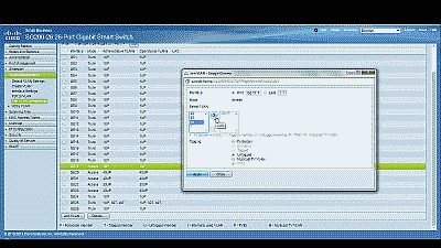
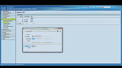
Begin by navigating to VLAN Management->Create VLAN and select “Add.” Enter a value of 50 in the “VLAN ID” field and enter a name to denote this particular VLAN in the “VLAN Name” field. In this example, we’ve used the name “vlan50.” When complete, select “Apply”. (See Figure 1)

Screenshot showing the creation of a new VLAN ID 50 in the Cisco SG200-26 switch

Figure 1

Before assigning membership of a particular port to our new VLAN, we must first configure that port to be either an “Access” port or a “Trunk” port. Access ports are ports that are members of only one VLAN. This type of port is normally used for attaching end devices which are generally unaware of a VLAN membership, either because their NIC is incapable of tagging Ethernet frames a VLAN ID, or they are not configured to do so. Switch ports configured as Access ports remove any VLAN information from the Ethernet frame before it is sent to the device. Trunk ports on the other hand can carry multiple VLAN traffic, and are normally used to connect switches to other switches or to routers. It is very often the case that small-business grade switches, such as the Cisco SG200, designate each port as a Trunk port by default.

To keep our example simple, we’ll assume that the device(s) connected to the switch are not configured, or are unable to be configured, to tag Ethernet frames with a VLAN ID. Consequently, in this example, we’ll configure port 19 as an Access port, and assign it membership in our newly created VLAN. Furthermore, we’ll also assume that port 25 is currently being used to connect the switch to the pfSense LAN interface, and configure it as a Trunk port, assigning it membership in our newly created VLAN.

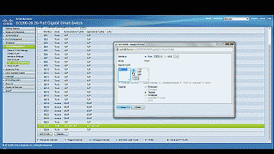
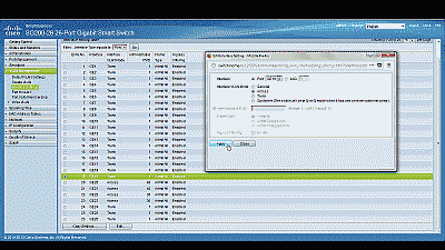
Navigate to VLAN Management->Interference Settings, select port 19 and then select “Edit”. Change the Interface VLAN Mode from Trunk to Access, then select “Apply” (See Figure 2). Now follow similar steps to configure port 2 as an Access port.

Screenshot showing port 19 being configured as an Access port in the Cisco SG200-26 switch

Figure 2

Next, navigate to VLAN Management->Port VLAN Membership, select port 19 and then select “Join VLAN”. Since Access ports can be added as untagged to only a single VLAN, we’ll need to first remove the default VLAN the switch automatically assigns to each port (usually VLAN 1). Highlight VLAN 1 by left-clicking on it, then select the arrow icon to remove it from the interface. Now highlight VLAN 50 by left-clicking on it, then select the arrow icon to add it to the interface, ensuring that “Untagged” is selected from among the options under “Tagging”. Select “Apply” when completed (See Figure 3).

Screenshot showing port 19 being joined to VLAN 50 in the Cisco SG200-26 switch

Figure 3

With switch port 19 configured as an Access port and joined to VLAN 50 any Ethernet frames that enter that port will be tagged with the appropriate VLAN ID. Now let’s configure the port 25, the port that is connected to the LAN NIC in pfSense. This port will be configured as a Trunk port and joined to VLAN 50 so that, in addition to passing the Ethernet frames from from devices attached to the other ports on the switch to pfSense, it will also pass Ethernet frames tagged with VLAN ID 50 entering switch port 19.

Ensure that port 25 is configure as a Trunk port, then navigate to VLAN Management->Port VLAN Membership, select port 25 and then select “Join VLAN”. Highlight VLAN 50 by left-clicking on it, then select the arrow icon to add it to the interface, ensuring that “Tagged” is selected from among the options under “Tagging”. Select “Apply” when completed (See Figure 4).

Screenshot showing port 25 being joined to VLAN 50 in the Cisco SG200-26 switch

Figure 4

That’s it for configuring the switch. If your switch supports both a running configuration and a startup configuration, make sure to save the changes you’ve made to the startup configuration so that they are not lost should the switch reboot for any reason.

Configuring pfSense

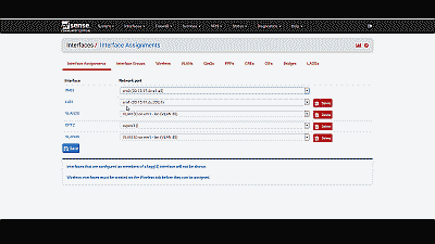
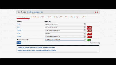
Now we need to create and configure VLAN 50 in pfSense. Navigate to Interfaces->Assignments and make note of the device driver name assigned to the LAN NIC. For this example we’ll assume the device driver name is “em1” (See Figure 5). The LAN interface will serve as the “parent interface” for the VLAN interfaces we will create in the next step.

Screenshot showing the device driver name assigned to the LAN NIC in pfSense

Figure 5

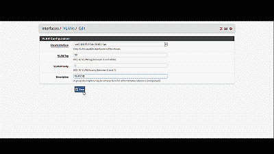
Next, navigate to Inerfaces->Assignments->VLANs and select the “+ Add” icon. In the subsequent screen, select “em1”, the LAN NIC interface, from among the options in the drop down list under “Parent interface”, and enter the value of 50 under “VLAN tag”. Add an optional description for this VLAN under “Description”, then select “Save” (See Figure 6).

Screenshot showing the configuration of a VLAN interface in pfSense

Figure 6

After creating the VLAN interface, return to Interfaces->Assignments and select the “+ Add” icon to add the “VLAN 50 on em1-lan (VLAN 50)”, then select “Save” (See Figure 7). At this point you’ll notice that under the “Interface” column pfSense has likely denoted VLAN 50 as an optional or “OPT” interface. Don’t worry, we’ll address that next.

Screenshot showing the addition of a VLAN interface in pfSense

Figure 7

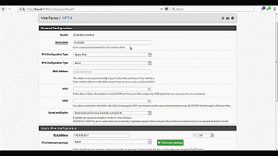
For this example we’ll assume that pfSense has assigned VLAN 50 as OPT4. Navigate to Interfaces->OPT4 and select “Enable Interface”. Under “Description” replace “OPT4” with “VLAN 50”, then select “Static IPv4” from among the options in the drop down list under “IPv4 Configuration Type”. We’ll use network 192.168.50.0/24 for VLAN 50 by assigning the static IP address 192.168.50.1 on this interface, and selecting the network mask of “24” under the “Static IP Configuration” section. The other parameters can remain at their default values. Select “Save” and “Apply changes” when complete (See Figure 8). Now if you navigating back to Interfaces->Assigments you will see VLAN 50 listed and labeled with the description you added when enabling the interface in the previous steps.

Screenshot showing the VLAN 50 interface being enabled in pfSense

Figure 8

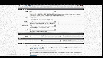
Next, we need to build a firewall rule for our two new VLANs so that traffic can pass to / from the WAN interface, and by extension, to the Internet. Navigate to Firewall->Rules and select the VLAN 50. Select the “Add” icon (there are currently no rules so either Add icon will work) to create a new rule. For our example, we’ll build a simple outbound pass rule for any protocol in VLAN 50, similar to the way a typical LAN outbound pass rule would be configured. Select “any” from among the options in the drop down list Under “Protocol”, and under “Source” select “VLAN50 net” from among the options in the drop list. If desired, you may enter a description of this newly created rule for your reference under “Extra Options”. The other parameters can remain at their default values. Select “Save” and “Apply changes” when complete (See Figure 9).

Screenshot showing the creation of a firewall rule for VLAN 50 in pfSense

Figure 9

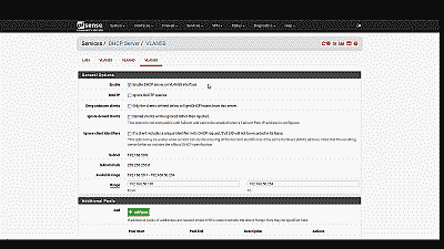
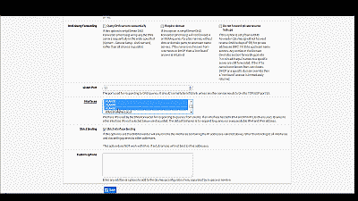
Unless you plan to assign static IP addresses to host devices, you’ll want to configure a DHCP server for the new VLAN 50. Navigate to Services->DHCP server and select VLAN 50. Select “Enable DHCP server on VLAN50 interface”, then enter the range of IP addresses within the network 192.168.50.0/24 you’d like the DHCP server to use under “Range”. Finally, pfSense will use the IP address assigned to this interface as the gateway address by default. For our example this address will be 192.168.50.1. If your requirements call for something different, enter an IP address for the network gateway under “Gateway”. The other parameters can remain at their default values. Select “Save” when complete (See Figure 10).

Screenshot showing the creation and configuration of a DHCP server for VLAN 50 in pfSense

Figure 10

You’ll also want to navigate to Services->DNS Forwarder->Interfaces and ensure that interfaces used by the DNS Forwarder for responding to queries from clients includes VLAN50, then select “Save” and “Apply changes” when complete (See Figure 11).

Screenshot showing the inclusion of the VLAN 50 interface in the DNS Forwarder in pfSense

Figure 11

Wrapping up

At this point the LAN switch and pfSense should be configured to support VLAN 50. To test, connect a host device such as a desktop or laptop computer to port 19 on the switch. If you’ve configured everything as described, you should receive an IP address within the DHCP address range you’ve specified for VLAN 50 network 192.168.50.0/24. The default gateway, DHCP server and DNS server addresses should be 192.168.50.1. You should also have Internet connectivity.

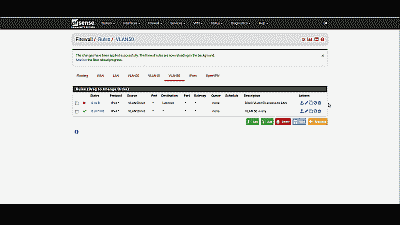
Be aware that as currently configured, each VLAN is routed to all other VLANs. If you would like to disallow some or all traffic to/from a particular VLAN you must create firewall rules explicitly stating what traffic should not be routed. Keep in mind that pfSense evaluates firewall rules on a first-match basis (i.e. the action of the first rule to match a packet will be executed). So, for example, if you wanted to block all VLAN 50 traffic from reaching the LAN you might create a rule to that effect before the one we created previously to route all VLAN 50 traffic to any destination (See Figure 12).

Screenshot showing the placement of a firewall rule blocking all traffic in VLAN 50 from reaching the LAN in pfSense

Figure 12

Conclusion

VLAN support in pfSense is not hard to configure nor complicated to manage, assuming your switch and NICs support this capability. To help explain the steps involved, we created a static VLAN on a commodity 24-port small-business switch and trunked that VLAN to the LAN interface on pfSense. We then created and added the VLAN interface, created the requisite firewall rules, and assigned the VLAN a unique /24 private IP subnet with host addressing handled using DHCP. The VLAN is able to share the pfSense’s Internet connection and we are able further configure pfSense to prevent routing traffic between each VLAN, if desired.
bookmark_borderHow To Access Your VirtualBox Guest VM From The Host Using SSH

(20180430 — The steps in this post were amended to address changes in recent versions of software — iceflatline)

Recently I had the occasion to spin up a Ubuntu server Virtual Machine (“VM”) in VirtualBox on a Windows-based host machine. Those of you who have performed a similar excercise know that the default window size that VirtualBox provides to command-line-based VMs, like *BSD and Ubuntu server, etc., is rather small, somewhere in neighborhood of the standard VGA resolution of 640 x 480 pixels. Normally the fix for this, of course, would be to install what VirtualBox calls “Guest Additions,” which consists of device drivers and other applications that optimize the guest operating system for, among other things, the ability to enlarge the window size. However, getting Guest Additions to install and run properly on command-line-based guest VMs is a monumental pain in the ass. One work-around that seems to work fairly well is to switch the VM window to “scale mode” (View->Switch to Scale Mode or Host+C), resulting in what is essentially a magnified version of the window and its contents. An even better solution, in my opinion, is to configure the VM so that you can connect to it directly from the host machine using Secure Shell (“SSH”), giving you full control over the window and text size of the guest VM.

This post explains how to access a VirtualBox Ubuntu server guest VM from the VirtualBox host machine using SSH. It then goes on to explain how to accomplish the same task when using a FreeBSD guest VM. The software versions used in this post were as follows:

  • FreeBSD 11.0-RELEASE
  • Ubuntu Server 18.04 LTS
  • VirtualBox 5.2.6

Let’s get started…

First, let’s add a new “VirtualBox Host-Only Ethernet Adapter” in VirtualBox. This new adaptor will allow us to enable a private network consisting of our host machine and our guest VM. The host can connect to any guest VMs configured to use this adaptor, and they can connect to each other, but nothing outside of this virtual network will be permitted access.

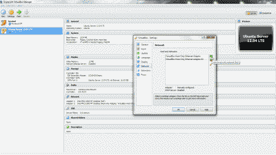
Navigate to Files->Preferences->Network and click on the “+” icon to add new adaptor. You’ll see that VirtualBox creates a new adaptor called “VirtualBox Host-Only Ethernet Adapter #2” (See Figure 1).

Screenshot showing the creation of a VirtualBox Host-Only Ethernet Adapter in VirtualBox

Figure 1

Right now you might be thinking “but couldn’t I just use the existing default VirtualBox Host-Only Ethernet Adaptor?” You absolutely could; however, setting up a second one allows you to customize it to your liking, leaving the default adaptor in its default configuration as a fallback.

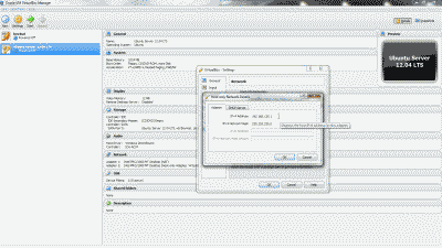
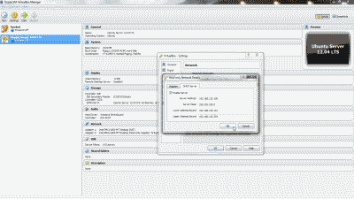
Now, double-click the new adaptor (or highlight it and select the edit icon) and note the IP address and subnet mask (e.g., 192.168.135.1 and 255.255.255.0) that VirtualBox has arbitrarily assigned under the “Adapter” tab. You may change these network parameters if desired, however, it is preferable to retain “1” as the value of the last octet in the IP address (See Figure 2).

Screenshot showing the IP address and subnet mask assignment in the VirtualBox Host-Only Ethernet Adapter #2

Figure 2

Optionally, you may configure a DHCP server on the VirtualBox Host-Only Ethernet Adapter #2 so that the guest VM obtains an IP address automatically at boot time. This can be accomplished by navigating to Files->Preferences->Network, double-clicking the new adaptor (or highlighting it and selecting the edit icon), selecting the “DHCP Server” tab and the selecting “Enable Server”. You’ll then need to modify the various DHCP server parameters (e.g., Server Address, Server Mask, etc.), keeping in mind that they should encompass the IP address configured for the adaptor, else the IP address should be modified so that it lies within the DHCP server parameters you’ve configured. When finished, select “OK” (See Figure 3). Note: I typically forgo using the DHCP server, electing instead to use a static IP address. That way, I can consistently use the same address each time I want use SSH to connect to the guest VM.

Screenshot showing the DHCP server configuration tab in the VirtualBox Host-Only Ethernet Adapter #2

Figure 3

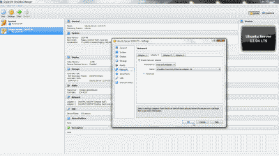
Let’s configure our Ubuntu server VM so that it will use the new VirtualBox Host-Only Ethernet Adapter #2. Shutdown the Ubuntu server VM if it’s running. Right-click on the VM and select Settings->Network. Select the “Adapter 2” tab, then select “Enable Network Adapter”. From among the options under “Attach to:”, select “Host-Only Adapter”, then select “VirtualBox Host-Only Ethernet Adapter #2” from among the options under “name:”. Now select “OK” (See Figure 4).

Screenshot showing the selection of VirtualBox Host-Only Ethernet Adapter #2 for use by the Ubuntu server virtual machine

Figure 4

Now start the Ubuntu server VM. After the system has fully booted, login to the VM at the VirtualBox console window and execute the command ifconfig -a to list all network devices. In addition to your primary network device, enp0s3 (in this example), you should now see a second network device listed, enp0s8 (in this example). If you chose to setup a DHCP server when creating VirtualBox Host-Only Ethernet Adapter #2, then enp0s8 should already have an IP address assigned to it from among the pool of addresses you chose to use with setting up the DHCP server, in which case you should make a note of this address and use it to connect to the Ubuntu server VM using SSH.

If you elected not to setup a DHCP server when creating VirtualBox Host-Only Ethernet Adapter #2, then you’ll need to assign a static IP address to network device enp0s8. First, install the package ifupdown:

Then open /etc/network/interfaces as the root user and add the following lines, making sure to change the values shown in this example so that they fall within the IP subnet parameters chosen when creating the new VirtualBox Host-Only Ethernet Adapter #2:

Now start the interface so that it obtains the new network parameters:

At this point you should be able to connect to the Ubuntu server VM via SSH using this static IP address.

FreeBSD Guest VM

A similar approach can be taken for a FreeBSD guest VM. The setup and configuration of the VirtualBox Host-Only Ethernet Adapter in VirtualBox is identical to what has been described thus far for the Ubuntu server VM. However, in order to assign a static IP address to the new network interface, em1 in the case of FreeBSD, you’ll need to open /etc/rc.conf as the root user and add the following line, making sure to change the values shown in this example so that they fall within the IP subnet parameters chosen when creating the new VirtualBox Host-Only Ethernet Adapter #2:

Then restart the interface so that it obtains the new network parameters:

Conclusion

The default window size that VirtualBox provides to command-line-based guest VMs like BSD and Ubuntu servers is typically very small, resulting in a poor user experience for those administrators trying to perform work beyond just a few quick simple commands. Fortunately, VirtualBox can be configured so that the user can connect directly to a guest VM from the host machine using SSH, giving the user full control over window and text sizing.

bookmark_borderHow to Create and Maintain a ZFS Mirror in NAS4Free

NAS4free is an open source NAS (“Network Attached Storage”) platform based on FreeBSD that supports file sharing across Windows, Apple, and UNIX-like systems. Support for ZFS, Software RAID (0,1,5), disk encryption, S.M.A.R.T, email reports, CIFS FTP, NFS, TFTP, AFP, RSYNC, Unison, iSCSI, HAST, CARP, Bridge, UPnP, and Bittorent, are among its many features – all configurable through its GUI interface. NAS4Free can be installed on Compact Flash or USB flash drive, hard disk or booted into a “LiveCD” environment. NAS4Free code and documentation are released under the Simplified BSD License.

The ZFS (“Zetabyte File System”) is a combined file system and logical volume manager designed by Sun Microsystems. The features of ZFS include protection against data corruption, support for high storage capacities, snapshots and clones, continuous integrity checking and automatic repair. ZFS is implemented as open-source software, licensed under the Common Development and Distribution License (CDDL).

This post will describe how to setup a simple, yet resilient, ZFS-based RAID 1 (ZFS mirror) in NAS4Free. In RAID 1, data is written identically to two disk drives, thereby producing a “mirrored” set. If one disk becomes defective, the remaining disk still contains all the data. To help explain the steps involved, we’ll use two new 2TB (Terabyte) SATA 3.0 hard disks, along with the ZFS utilities available within NAS4Free, to create and configure our ZFS mirror. We’ll also discuss a few post-install activities to help maintain your ZFS mirror. All steps involved assume that the two hard drives have been installed correctly and are recognized by the BIOS, and that NAS4Free is installed and operational. The software versions used in this post were as follows:

  • NAS4Free v9.1.0.1 – Sandstorm (revision 636)

So, let’s get started.

Adding the Disks

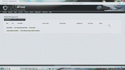
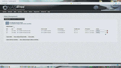
The first thing we need to do is logically add the two new disks to NAS4Free so the system acknowledges their existence, permitting further configuration on them. Log in to the NAS4Free GUI (“Graphical User Interface”), navigate to Disks->Management, and select the “+” icon. (See Figure 1).

Screenshot showing the Disk Management page in NAS4Free

Figure 1

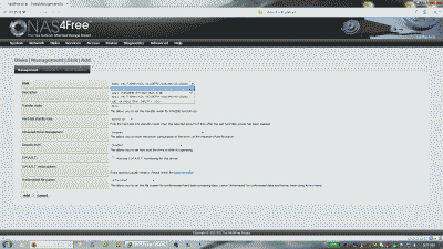
In the subsequent page you are presented with the configuration screen for adding new disks. Select the first 2TB disk from the drop-down menu under the “Disk” field, and select “unformatted” from among the options in the drop-down menu under the “Preformatted file system” field. The remaining options on this page can retain their default settings. Now select “Add” (See Figure 2).

Screenshot showing the Disk Management - Add Disk page in NAS4Free

Figure 2

Repeat these steps for the second 2TB disk. When complete, select “Apply changes” (See Figure 3).

Screenshot showing the Disk Management page in NAS4Free indicating that two new disks have been added

Figure 3

Note: If you’re adding disks that have previously been formatted using ZFS, NAS4Free will likely not allow you to add these disks as unformatted. You can, however, add them by selecting “zfs storage pool device” under the “Preformatted file system” field and skip the following formatting step.

Format the Disks

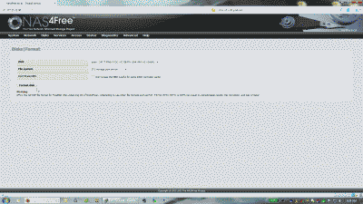
Now that the disks have been added, we need to format them. Navigate to Disks->Format, and select one of the newly added disks from the drop-down menu under the “Disk” field. Select “ZFS storage pool device” from the drop-down menu under the “File system” field, then select “Format disk” (See Figure 4).

Screenshot showing a newly added disk being formatted as a ZFS storage pool device in NAS4Free

Figure 4

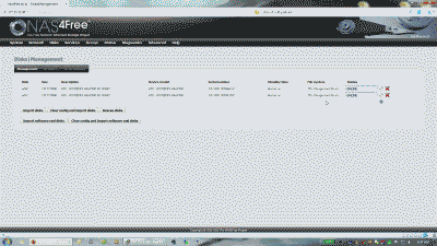
Repeat these steps for the second disk, then navigate back to Disks->Management and ensure that both disks are present and formatted as ZFS storage pool devices (See Figure 5).

Screenshot showing two newly added disks formatted as a ZFS storage pool device in NAS4Free

Figure 5

Create a ZFS Virtual Device

We’ve added our two 2TB hard disks and formatted them. Now its time to create a ZFS “vdev” or virtual device.

Unlike traditional file systems, which reside on single devices and require a volume manager to use more than one device, ZFS filesystems are built on top of virtual storage pools called “zpools.” A zpool is constructed of virtual devices, or “vdevs,” which are themselves constructed of block devices: files, hard disk partitions, or entire disks, with the latter being the recommended usage. Block devices within a vdev may be configured in different ways, depending on needs and space available: non-redundantly (similar to RAID 0), as a mirror (RAID 1) of two or more devices, which is the focus of this post, or as a RAID-Z (similar to RAID-5) group of three or more devices.

In summary then, a vdev represents the disk drives that are used to create a zpool. A zpool can have any number of vdevs at the top of the configuration, known as a “root vdev.” If the top-level virtual devices contain two or more physical devices, the configuration provides data redundancy as mirror or RAID-Z virtual devices.

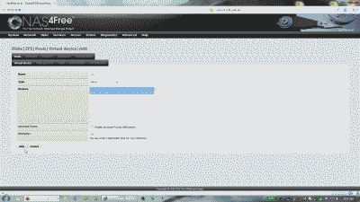
To create a virtual device consisting of our newly added hard disks, navigate to Disks->ZFS->Pools->Virtual device, and select the “+” icon. In the subsequent page, enter a name for the new virtual device under the “Name” field (e.g., “vd_1”), and select “Mirror” from among the options under the “Type” field. Now select both hard disks in the “Devices” field by holding the CTRL key and left-clicking each disk. You can also enter a description for the virtual device under the “Description” field, if desired. Select “Save” when complete (See Figure 6).
Screenshot showing the creation of a ZFS virtual device in NAS4Free

Figure 6

Create a ZFS Pool

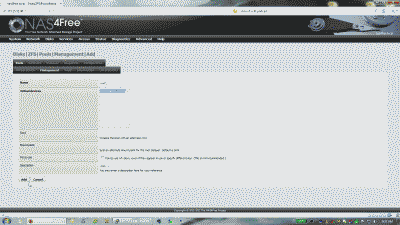
Having created our vdev, let’s move on and create a zpool. Navigate to Disks->ZFS->Pools->Management, and select the “+” icon. In the subsequent page, enter a name for the new zpool under the “Name” field (e.g., pool_1). You should see the vdev created previously listed under the “Virtual devices” field. Select the vdev by left-clicking on it. Add a description for the virtual device under the “Description” field if desired. The remaining options can retain their default settings, resulting in the mount point for the zpool becoming /mnt/[your-zpool-name]. Select “Save” when complete (See Figure 7).
Screenshot showing the creation of a ZFS zpool in NAS4Free

Figure 7

Create a ZFS Dataset

At this point you could start using your entire zpool as storage if desired. However, a significant feature of ZFS is the concept of “datasets.” A dataset is essentially a child filesystem of the parent zpool. Imagine that the zpool is a single hard disk. In a typical hard disk you would create a single, disk-sized partition, and then format that partition with a filesystem. But if later you’d like to add additional filesystems to the disk, you have to erase and redo your partition to create more partitions to contain the new filesystems, or use a tool to actively resize existing partition, and then create the new partitions and filesystems.

With datasets, all of these partitioning efforts are unnecessary. A ZFS dataset acts like another mounted partition with no locked-in size. The quantity of disk space it takes up is only as much space as you use in populating it, or children datasets of it (of course, it can never be larger than the size of its parent zpool). You don’t have to worry about resizing partitions as ZFS inherently handles all that for you. Additionally, each dataset can have its own special configuration by modifying different behavioral variables. For example, you can determine quota and permissions independently for each dataset. Finally, datasets provide more flexibility if you need to snapshot or clone your filesystems.

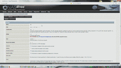
To add a dataset to the zpool, navigate to Disks->ZFS->Datasets->Dataset, and select the “+” icon. Enter a name (e.g., “files”) in the “Name” field (resulting in the mount point for the dataset becoming /mnt/[your-zpool-name]/[your-dataset-name]). Ensure that the zpool created previously is selected from the drop-down list under the “Pool” field. If you’re interested in performing periodic snapshots of the dataset (discussed below), I recommend enabling the “Snapshot Visibilty” option so that the snapshots are added automatically to /mnt/[your-zpool-name]/[your-dataset-name])/.zfs/snapshots. The remaining options can be configured according to your requirements. Select “Add” when complete (See Figure 8).

Screenshot showing the creation of a ZFS dataset in NAS4Free

Figure 8

Wrapping up

We’ve successfully added two new 2TB hard disks to NAS4Free and formatted them, created a vdev and a zpool, and finally, created a dataset within our zpool. At this point you can start enabling services such as CIFS, NFS, UPnP, etc., to take advantage of your new ZFS mirror storage. Remember, when configuring some of these services to select the correct mount point for your dataset (e.g., /mnt/pool_1/files).

With the creation and configuration of our ZFS mirror out of the way, let’s move on talk about a few maintenance activities that should prove useful.

    Replacing a defective hard disk

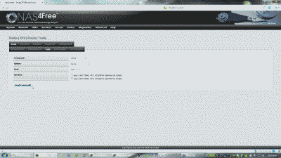
Occasionally you may have to replace a hard disk in your zpool that has become defective. To perform the replacement, navigate to Disks->ZFS->Pools->Information and note which disk is defective or missing (e.g. ada2). Next, navigate to Disks->ZFS->Pools->Tools and offline the disk if possible by selecting “offline” from the drop-down list under the “Command” field. Ensure that “Device” is selected under the “Option” field and that the correct pool is selected under the “Pool” field. Use the checkbox to select the defective disk under the “Devices” field, then select “Send Command!” (See Figure 9).

Screenshot showing a defective disk being offlined in NAS4Free

Figure 9

Power down NAS4Free, then identify and replace the defective disk with one of equal storage capacity using, if possible, the same SATA port [Pro-tip: Take the time to label your disks correctly (e.g. ada2) when you install them. It will make physically identifying the defective disk much easier!]. Restart NAS4Free and navigate to Disks->ZFS->Pools->Information to verify the device name for the new disk. If you were able to reuse the same SATA port, the device name should be same as the defective disk (e.g. ada2). Navigate to Disks->ZFS->Pools->Tools and replace the disk by selecting “replace” from the drop-down list under the “Command” field. Ensure that “Device” is selected under the “Option” field and that the correct pool is selected under the “Pool” field. Use the checkbox to select the defective disk under the “Devices” field and the new disk from the drop-down list under the “New Device” field, then select the “Send Command!” The replacement disk should resilver fairly quickly. Verify by navigating to Disks->ZFS->Pools->Information

    Creating and managing snapshots

One of the many great features about using ZFS is its snapshot capability. A snapshot is a read-only reference to the state of a dataset at the moment the snapshot was taken. It is a reference, and not copy, because at the moment it is taken, it takes up no additional space. However, as data within the dataset changes, either because files are modified or deleted, the snapshot consumes disk space by continuing to reference the old data. This behavior allows you to easily recover files if necessary, but in doing so prevents disk space from being freed until the snapshot is deleted.

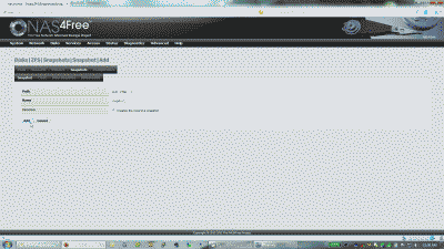
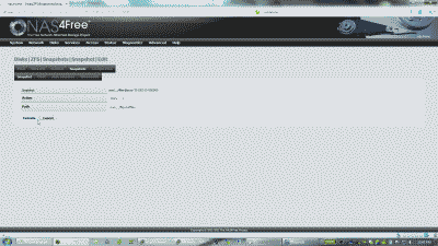
To take a snapshot manually, navigate to Disks->ZFS->Snapshots->Snapshot, and select the dataset you want to snapshot (e.g., pool_1/files) from under the “Path” field. Enter a name for the snapshot (e.g., snapshot_1), enable “Recursive” option, then select “Add” (See Figure 10).

Screenshot showing a ZFS snapshot being manually created in NAS4Free

Figure 10

NAS4Free also provides the ability to configure reoccurring snapshots under Disks->ZFS->Snapshots->Auto Snapshot. Here you can schedule a time the system should perform the snapshot and how long it should retain them, resulting in the oldest snapshot being deleted when the deadline is reached.

You have a couple of options when it comes to “rolling back” to a particular snapshot. In fact, though , rolling back is a slight misnomer, because what you’re really doing is locating the snapshot you’re interested in and copying over the files you’d like to recover. If you selected the option “Snapshot Visibility” when setting up your dataset in NAS4Free (See Disks->ZFS->Datasets->Dataset->Edit), then all snapshots for that dataset will be located in that filesystem under the directory /.zfs/snapshot (e.g., /mnt/pool_1/files/.zfs/snapshot). This allows you to simply navigate to the snapshot directory your interested in and copy files from that directory to the current filesystem.

Another way you can recover files from snapshots is to clone one to another directory. This approach has the advantage of allowing you to share out the cloned snapshot directory, say using CIFS or NFS, for some period of time until files are recovered. To clone a snapshot, navigate to Disks->ZFS->Snapshots->Snapshot and edit the snapshot you’re interested in cloning by selecting the small wrench icon. Ensure that “Clone” is selected under the “Action” field, then enter a path to the directory where the clone is to reside. Note that this path must be expressed as a relative path. So, for example, pool_1/files/oldfiles would work, but /mnt/pool_1/files/oldfiles would not, nor would /pool_1/files/oldfiles. Also note that the directory where the snapshot will be cloned does not have to be created in advance, rather it will be created automatically for you when you clone the snapshot. Now, select “Execute” when finished and your cloned snapshot will be available for use at the path you specified (e.g. /mnt/pool_1/files/oldfiles) (See Figure 11). Cloned snapshots can be destroyed at anytime by navigating to Disks->ZFS->Snapshots->Clone.

Screenshot showing a snapshot clone being manually created in NAS4Free

Figure 11
    Data scrubbing

Performing a ZFS “scrub” on a regular basis helps to identify data integrity problems, detect silent data corruptions caused by transient hardware issues, and to provide early alerts to disk failures. This operation traverses all the data in the zpool once and verifies that all blocks can be read. Scrubbing proceeds as fast as the vdevs will allow, though the priority of any disk I/O generally remains below that of normal operations. So, while the scrub operation might negatively impact performance slightly, the zpool’s data should remain usable and nearly as responsive while the scrubbing occurs.

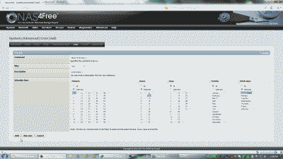
To schedule and manage scrubs on a ZFS zpool in NAS4Free, we’ll set up a cron job to run the zpool scrub command. Navigate to System->Advanced, and select the Cron tab. Ensure that the “Enable” checkbox is selected, then enter the command zpool scrub [your-pool-name] in the “Command” field. Ensure that the command is run as the root user and enter a description for the cron job if desired. Now select when you’d like the command to run in the “Scheduled time” field. If you have consumer-quality drives, consider a weekly scrubbing schedule. If you have data center-quality drives, consider a monthly scrubbing schedule. Also note that depending upon the amount of data in the zpool, a scrub can take a long time. Consequently, you may want to consider scheduling them for evenings or weekends to minimize the impact on performance. When complete, select “Add”, then “Apply changes”. The example shown in Figure 12 shows the command zpool scrub pool_1 will run every Sunday at 1300 local time.

Screenshot showing ZFS scrubbing being configured as a cron job in NAS4Free

Figure 12

Conclusion

This post described how to create and maintain a simple, yet resilient, ZFS mirror in NAS4Free, an open source NAS implementation based on FreeBSD.

bookmark_borderCheck if a Device or File System is Mounted

Occasionally I find myself needing to mount a remote file system on a local *BSD or Linux machine. On one such occasion recently I had mounted an NFS file system from a Network Attached Storage (NAS) server to a local machine running FreeBSD, for the purpose of backing up some of the files to yet another machine offsite using the rsync utility. I had created a little script to run rsync periodically through cron. This script worked well until I noticed a few days later that the backups on the remote machine no longer existed. After some investigation I quickly determined that NAS file system was no longer mounted on the FreeBSD machine (I can neither confirm or deny that I may have configured something incorrectly). The rsync script, upon noticing that files no longer existed in the source, deleted said files at the target. It was at that point that I decided to include a small test in the rsync script to check on the existence of the mounted file system; then, if it still existed, the script would proceed with the rsync command, else it would write an error message to a log. Here is the code snippet I used in the script, which you can easily adapt for other situations:

The df command simply displays statistics about the amount of free disk space on the specified file system. If a file system argument is not specified, statistics for all mounted file systems are displayed. The output of the df command is then piped through the venerable grep utility using its -q option, which instructs grep not to write anything to standard output, but rather exit immediately with a zero status if a match is found. Finally, the file system we’re interested in matching to, parsed from the output of the df command, is provided to grep. If the output of this df command is zero, the script runs a command (in this case my rsync command), else if it exits with anything other than zero, the script runs another command instead (in this case an error message).

bookmark_borderHow to Use Portmaster to Update Ports

(20170315 — The steps in this post were amended to address changes in recent versions of software — iceflatline)

The Ports Collection is a set of Makefile, patches, and description files stored in /usr/ports. This set of files is used for building and installing applications on FreeBSD, and other BSD-based operating systems.

This post will describe how to use portmaster, a utility for updating installed ports. portmaster is nothing more than a shell script (albeit a quite elegant and powerful one), written in /bin/sh. It does not depend upon other ports, external databases or languages, rather it’s been written in such a way as to make use of the information about a port’s dependencies, dependents, file locations and other information contained in /var/db/pkg to determine which ports to update.

The versions of software discussed in this post are as follows:

  • FreeBSD 11.0-RELEASE
  • portmaster-3.17.10

Okay, let’s get started. All commands are issued as the root user or by simulating the root user by using the command su. Let’s make sure that the Ports Collection is updated to its most current version with the following command:

If you haven’t installed portmaster yet, let’s do that now. You’ll be prompted with several configuration options. Select any options you’d like and select “OK”:

Now that the Ports Collection has been updated and portmaster installed, let’s check the installed ports against the updated Ports Collection to see whether any installed ports need to be updated. portmaster provides a way to list ports that need updating using the -L option:

As you’ll see in the corresponding output of this command that portmaster groups all installed ports into four categories:

Root ports: port listed under this category have no dependencies, nor are they depended on by other ports.

Trunk ports: ports listed under this category have no dependencies, but other ports depend upon them.

Branch ports: ports listed under this category have dependencies and are also depended upon by other ports.

Leaf ports: Ports listed under this category have dependencies but are not depended upon by other ports.

Each installed port will be listed in one of these categories along with whether the port has a revised version available:

Following the list portmaster will present a succinct summary of the status of your ports:

Before updating a particular port or ports, it’s a good idea to check the notes contained in /usr/ports/UPDATING to see if there are any issues related to updating one or more of them. /usr/ports/UPDATING contains all the last minute notes on all of the ports in the Ports Collection and documents, where applicable, some of the problems you may encounter when updating, and/or additional features or options that may be available. Follow the instructions contained in /usr/ports/UPDATING to update the affected ports. In most every case there will be instructions for how to use portmaster to perform the task. The remaining ports can be updated using the following command:

The -d option tells portmaster to clean up the installation files (in /usr/ports/distfiles), which will help save some disk space. The -w option tells portmaster to save old shared libraries (in /usr/local/lib/compat/pkg/) before “deinstalling” the existing port, allowing those libraries to potentially be restored if there are any incompatibility issues between the new port and the installed libraries. Adding the -v option will direct portmaster to be a bit more forthcoming about what it’s doing. Finally, the name of the port should be one of the following: the full name of the port directory as specified in /var/db/pkg, for example apache22-2.2.23_3 or the full path to the port in the Ports Collection, for example /usr/ports/www/apache22.

After entering the command above portmaster will recurse through the port and its dependencies (if any) to handle any configuration options. If configuration options have changed since the last time the port was updated, portmaster will likely prompt for input. However, you can force the configuration dialogs for all ports by adding the force-config option to the command:

If none of the port’s dependencies require updating, portmaster will simply download the necessary source files and perform the update, otherwise you will be presented a list of ports that will be updated and asked to confirm before portmaster proceeds. You can skip the confirmation step by adding the no-confirm option to the command:

You can also update all of the outdated ports at once using the following command:

The -a options tells portmaster to review all installed ports and update them if necessary. Once again, if portmaster is unclear about the configuration options for a particular port, it will prompt for input, otherwise it will present a list of ports that it will update and ask to confirm before proceeding. The force-config and no-confirm options can be used here as well, if desired.

Adding the -x option will direct portmaster to avoid building or updating ports that match a pattern. For example, the following will update all installed ports except apache22:

The portmaster utility also provides some other useful functions. For example, portmaster can be used as a port installation tool by executing it as though you were updating a port. portmaster will recognize that it’s a new port and install the port’s dependencies as usual:

Sometimes it’s helpful to have portmaster figure out what needs to be updated and in what order, but not actually do it. Adding the -n option directs portmaster to run through the configuration, but not actually update or install any ports

There you have it. The portmaster utility is a simple yet powerful tool for updating your ports. It does not depend on other software or use an external database to track what you have installed, but rather uses the existing ports infrastructure, including what is located in /var/db/pkg. This post covered the basics. The portmaster man page contains a lot more information about portmaster, how it works and what choices are available to you.

iceflatline